Concept explainers
Videos
4.23 and 4.24 For each of the plates and loadings shown, determine the reaction at A and B.
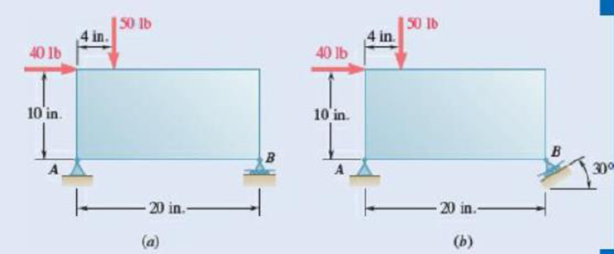
Fig. P4.23
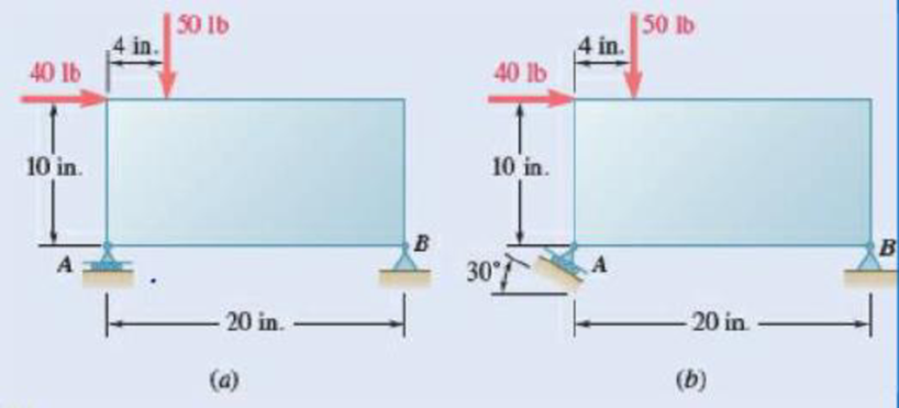
Fig. P4.24
(a)
The reaction at
Answer to Problem 4.23P
The reaction at
Explanation of Solution
Take vectors along positive
Let
The free body diagram is sketched below as figure 1.
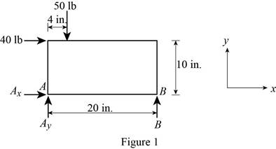
Here,
Write the expression for the moment at
Here,
Above equation implies that net moment at any point is the sum of product of each force acting on the system and perpendicular distance of the force and the point.
The moment at
Thus, the complete expression of
Here,
At equilibrium, the sum of the moment acting at
Write the expression for the net force along the
Here,
At equilibrium, the net force along the
Write the expression for the net force along the
Here,
At equilibrium, the net force along the
Let
Write the expression for the magnitude of net reaction at
Here,
Therefore, write the expression for the
Calculation:
Rearrange equation (III) to get
From figure 1, the reaction
Rearrange equation (V) to get
The negative sign indicates that the
Rearrange equation (VII) to get
Substitute
Substitute
Substitute
Therefore, the reaction at
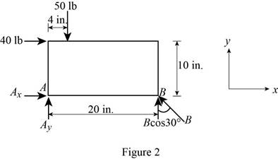
(b)
The reaction at
Answer to Problem 4.23P
The reaction at
Explanation of Solution
Take vectors along positive
Let
The free body diagram is sketched below as figure 2.
Here,
Write the expression for the moment at
Here,
Above equation implies that net moment at any point is the sum of product of each force acting on the system and perpendicular distance of the force and the point.
The moment at
Thus, the complete expression of
Here,
From figure 2 , u component of reaction
At equilibrium, the sum of the moment acting at
Write the expression for the net force along the
Here,
At equilibrium, the net force along the
Write the expression for the net force along the
Here,
At equilibrium, the net force along the
Let
Write the expression for the magnitude of net reaction at
Here,
Therefore, write the expression for the
Calculation:
Rearrange equation (III) to get
From figure 2, the reaction B is
Rearrange equation (V) to get
Substitute
Rearrange equation (VII) to get
Substitute
Substitute
Substitute
Therefore, the reaction at
Want to see more full solutions like this?
Chapter 4 Solutions
EBK VECTOR MECHANICS FOR ENGINEERS: STA


- Fig. P4.154, P4.155 4.155 Assuming that P= 48000 lb and that it may be applied at any joint on the line FJ, determine the location of P that would cause (a) maximum tension in member HI; (b) maximum compression in member CI; and (c) maximum tension in member CI. Also determine the magnitude of the indicated force in cach case.arrow_forwardFor the frame and loading shown, determine the reactions at C and D. 150 lb A -3 ft Fig. P4.68 B -3 ft D 1.5 ft 15 ftarrow_forwardDetermine the reactions at A and B when (a) α=0, (b) α=90°,(c) α=30°.arrow_forward
- 5 panels e L= SL W 45 Fig. P4.168 4.168 A couple acting on the winch at G slowly raises the load W by means of a rope that runs around the pulleys attached to the derrick at A and B. Determine the forces in members EF and KL of the derrick, assuming the diameters of the pulleys and the winch are negligible. %3B O 8 O O O Oarrow_forwardRod ABC is bent in the shape of an arc of circle of radius R . Knowing that 0= 60°, determine the reaction (a) at B, (b) at C.arrow_forwardProblem 4.30 4.30 The horizontal force P is applied to the handle of the puller. Determine the resulting tension T and all the other reactions as necessary. P = 120 lb Coplanar system, one rigid body, two supports, one 24 in. external load. B В 40° 20° A -6 in.-arrow_forward
- 4.63 Horizontal and vertical links are hinged to a wheel, and forces are applied to the links as shown. Knowing that a = value of P and the reaction at A. 100 mm 100 mm 75 mm, determine the a В 100 mm 90 N Fig. P4.63 and P4.64arrow_forwardNeglecting friction, determine the tension in cable ABD and the reaction at C w hen 0=45°.Fig. P4.34arrow_forwardFor each of the plates and loadings shown, determine the reactions at A and Barrow_forward
- 1.Determine the reactions at A and B when (a) a = 0, (b) a = 90°, (c) a = 30°. 330 N -250 mm-250 mm- B 300 mm Aarrow_forwardDetermine the reactions at A and B when (a) a= 0, (b) a = 90°, (c) a = 30°.arrow_forward50 N -450 mm SOLUTION 100 N 450 mm 150 N B 50N PROBLEM 4.13 The maximum allowable value of each of the reactions is 180 N. Neglecting the weight of the beam, determine the range of the distance d for which the beam is safe. 100N IOON, et -d-4 +0.45m 150N 0.45'm ΣF = 0 B =0 3*arrow_forward
 Elements Of ElectromagneticsMechanical EngineeringISBN:9780190698614Author:Sadiku, Matthew N. O.Publisher:Oxford University Press
 Mechanics of Materials (10th Edition)Mechanical EngineeringISBN:9780134319650Author:Russell C. HibbelerPublisher:PEARSON
 Thermodynamics: An Engineering ApproachMechanical EngineeringISBN:9781259822674Author:Yunus A. Cengel Dr., Michael A. BolesPublisher:McGraw-Hill Education
 Control Systems EngineeringMechanical EngineeringISBN:9781118170519Author:Norman S. NisePublisher:WILEY
 Mechanics of Materials (MindTap Course List)Mechanical EngineeringISBN:9781337093347Author:Barry J. Goodno, James M. GerePublisher:Cengage Learning
 Engineering Mechanics: StaticsMechanical EngineeringISBN:9781118807330Author:James L. Meriam, L. G. Kraige, J. N. BoltonPublisher:WILEY