Concept explainers
Videos
A truss can be supported in the eight different ways shown A connections consist of smooth pins, rollers, or short links. For case, answer the questions listed in Prob. 4.59, and, wherever possible, compute the reactions, assuming that the magnitude force P is 12 kips.
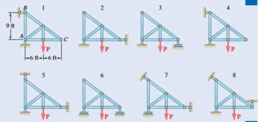
Fig. P4.60
(a)
Find whether the plate is completely, partially, or improperly constrained.
Answer to Problem 4.60P
The plate in figure 1 is
The plate figure 2 is
The plate figure 3 is
The plate figure 4 is
The plate figure 5 is
The plate figure 6 is
The plate figure 7 is
The plate figure 8 is
Explanation of Solution
Given information:
The magnitude of the force P is 12 kips.
Calculation:
Figure 1:
Show the free-body diagram of the Figure 1.
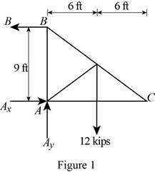
The three reactions in the plate behave like non-concurrent and non-parallel force system.
The plate in figure 1 is
Figure 2:
Show the free-body diagram of the Figure 2.
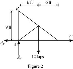
The three reactions in the plate behave like concurrent force system.
The plate figure 2 is
Figure 3:
Show the free-body diagram of the Figure 3.
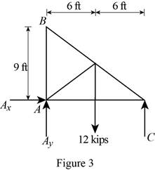
The three reactions in the plate behave like non-concurrent and non-parallel force system.
The plate figure 3 is
Figure 4:
Show the free-body diagram of the Figure 4.
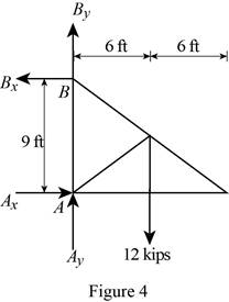
The four reactions in the plate behave like non-concurrent and non-parallel force system.
The plate figure 4 is
Figure 5:
Show the free-body diagram of the Figure 5.
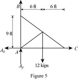
The four reactions in the plate behave like concurrent force system.
The plate figure 5 is
Figure 6:
Show the free-body diagram of the Figure 6.
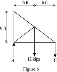
The two reactions in the plate behave like concurrent force system.
The plate figure 6 is
Figure 7:
Show the free-body diagram of the Figure 7.
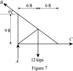
The three reactions in the plate behave like non-concurrent and non-parallel force system.
The plate figure 7 is
Figure 8:
Show the free-body diagram of the Figure 8.
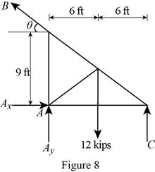
The four reactions in the plate behave like non-concurrent and non-parallel force system.
The plate figure 8 is
(b)
Find whether the reactions are statically determinate or indeterminate.
Answer to Problem 4.60P
The reactions in figure 1 is
The reactions in figure 2 is
The reactions in figure 3 is
The reactions in figure 4 is
The reactions in figure 5 is
The reactions in figure 6 is
The reactions in figure 7 is
The reactions in figure 8 is
Explanation of Solution
Refer Figure 1:
The equilibrium equations are;
The equilibrium equations are enough to determine the unknown reactions.
The reactions in figure 1 is
Refer Figure 2:
The equilibrium equations are;
The equilibrium equations are enough to determine the unknown reactions.
But the plate is improperly constrained and the plate is not in equilibrium.
The reactions in figure 2 is
Refer Figure 3:
The equilibrium equations are;
The equilibrium equations are enough to determine the unknown reactions.
The reactions in figure 3 is
Refer Figure 4:
The equilibrium equations are;
The equilibrium equations are not enough to determine the unknown reactions.
The reactions in figure 4 is
Refer Figure 5:
The equilibrium equations are;
The equilibrium equations are enough to determine the unknown reactions.
But the plate is improperly constrained and the plate is not in equilibrium.
The reactions in figure 5 is
Refer Figure 6:
The equilibrium equations are;
The equilibrium equations are enough to determine the unknown reactions.
The reactions in figure 6 is
Refer Figure 7:
The equilibrium equations are;
The equilibrium equations are enough to determine the unknown reactions.
The reactions in figure 7 is
Refer Figure 8:
The equilibrium equations are;
The equilibrium equations are not enough to determine the unknown reactions.
The reactions in figure 8 is
(c)
Find whether the equilibrium of the plate is maintained.
Answer to Problem 4.60P
The reactions in the plate 1 are
The plate 1 is in
The plate 2 is in
The reactions in the plate 3 are
The plate 3 is in
The reactions in the plate 4 are
The plate 4 is in
The plate 5 is in
The reactions in the plate 6 are
The plate 6 is in
The reactions in the plate 7 are
The plate 7 is in
The reactions in the plate 8 are
The plate 8 is in
Explanation of Solution
Refer Figure 1:
The equilibrium equations are;
Take moment about point A.
Resolve the horizontal component of forces.
Resolve the vertical component of forces.
Find the resultant force at A;
Find the angle
Therefore, the reactions in the plate 1 are
The plate 1 is in
Refer Figure 2:
The equilibrium equations are;
The moment about point A is not equal to zero.
The plate 2 is in
Refer Figure 3:
The equilibrium equations are;
Take moment about point A.
Resolve the horizontal component of forces.
Resolve the vertical component of forces.
Therefore, the reactions in the plate 3 are
The plate 3 is in
Refer Figure 4:
The equilibrium equations are;
Take moment about point A.
Resolve the horizontal component of forces.
Resolve the vertical component of forces.
Therefore, the reactions in the plate 4 are
The plate 4 is in
Refer Figure 5:
The equilibrium equations are;
The moment about point A is not equal to zero.
The plate 5 is in
Refer Figure 6:
The equilibrium equations are;
Take moment about point A.
Resolve the vertical component of forces.
Therefore, the reactions in the plate 6 are
The plate 6 is in
Refer Figure 7:
The equilibrium equations are;
Find the angle
Take moment about point A.
Resolve the horizontal component of forces.
Resolve the vertical component of forces.
Therefore, the reactions in the plate 7 are
The plate 7 is in
Refer Figure 8:
The equilibrium equations are;
Take moment about point C.
Therefore, the reactions in the plate 8 are
The plate 8 is in
Want to see more full solutions like this?
Chapter 4 Solutions
Loose Leaf for Vector Mechanics for Engineers: Statics and Dynamics


- For the bracket and loading of Prob. 4.7, determine the smallest distance a if the bracket is not to move.(Reference to Problem 4.7):A T-shaped bracket supports the four loads shown. Determine the reactions at A and B (a) if a = 10 in., (b) if a = 7 in.arrow_forwardSOLVE THE PROBLEMS WITH METHOD OF JOINTS AND METHOD OF SECTIONS 4.152 Compute the forces in members EF, NF, and NO. E F G n 5. M P 300 kN -8 pancls e 5 m = 40 m Dimensions in meters Fig. P4.152, P4.153 4.153 Repcat Prob. 4.152 assuming that the 300-kN force is applied at O instead of L.arrow_forward4.167 Determine the forces in members BC and BE and the horizontal pin reaction at G. 12000 Ib 16000 Ib 12000 Ib -8- Dimensions in feet Fig. P4.167arrow_forward
- ABC (fig. 3) is acted upon by a 455 N force. The pole is held by a ball and socket joint at A and by two cables BD and BE. For a = 3m, determine the tension in each cable, and the reactions (A., Aỳ and A.) at A:arrow_forwardThe press shown below is used to emboss a small metal plate at E. The press is composed of 3 members: handle ABC, link BD, and piston DE that are connected by pins at points A, B. and D. A vertical force of 250 N is applied at point C. Determine: (a) The vertical component of the force exerted on the plate at E and the reactions at pin A. (b) The mechanical advantage of the press. Draw all required FBD's and put units on your answers. A 200 mm 60° 19T 20° 400 mm 15⁰ C C Parrow_forwardQ.5) The bent bar as shown below is supported by a cable AE, a ball-and-socket joint at O, and a journal (slider) bearing at D. At the journal bearing D, the momen support reactions and the force support reaction along y-axis are zero. The 2-kip force and the 6 kip-ft couple-moment are parallel to z-axis and applied at point B. Determine the tension in the cable AE and the support reactions at O and D. X A / 0 4 ft Z 16 kip-ft 2 ft B 2 ft 2 kips BANES 3 ft [ 1 kip = 1000 lb. ] E 14 ft yarrow_forward
- Solve Prob. 4.115, assuming that the hinge at A has been removed and that the hinge at B can exert couples about axes parallel to the x and y axes.(Reference to Problem 4.115):The horizontal platform ABCD weighs 60 lb and supports a 240-lb load at its center. The platform is normally held in position by hinges at A and B and by braces CE and DE. . If brace DE is removed, determine the reactions at the hinges and the force exerted by the remaining brace CE . The hinge at A does not exert any axial thrust.arrow_forwardThe rectangular plate shown weighs 93 lb and is held in the position shown by hinges at A and B and by cable EF. Assuming that the hinge at B does not exert any axial thrust and no couples exerted on both A and B, determine (a) the tension in the cable, (b) the reactions at A and B. y Solution: 12 in. 30 in. H 4 in. E 8 in. B 4 in. 25 in. 20 in. Xarrow_forward10 5 panels e L= SL Solve using method of joints W 45/L Fig. P4.168 4.168 A couple acting on the winch at G slowly raises the load W by means of a rope that runs around the pulleys attached to the derrick at A and B. Determine the forces in members EF and KL of the derrick, assuming the diamcters of the pulleys and the winch are negligible.arrow_forward
- Problem 4.30 4.30 The horizontal force P is applied to the handle of the puller. Determine the resulting tension T and all the other reactions as necessary. P = 225 lb Coplanar system, one rigid body, two supports, one 24 in. external load. 40 22 A +6 in.-arrow_forwardThe frame for a sign is fabricated from thin, flat steel bar stock of mass per unit length 4.73 kg/m. The frame is supported by a pin at C and by a cable AB. Determine (a) the tension in the cable, (b) the reaction at C.arrow_forwardSolve Prob. 4.19, assuming that a= 0.32 m.(Reference to Problem 4.19):The bracket BCD is hinged at C and attached to a control cable at B . For the loading shown, determine (a) the tension in the cable, (b) the reaction at C.arrow_forward
 Elements Of ElectromagneticsMechanical EngineeringISBN:9780190698614Author:Sadiku, Matthew N. O.Publisher:Oxford University Press
 Mechanics of Materials (10th Edition)Mechanical EngineeringISBN:9780134319650Author:Russell C. HibbelerPublisher:PEARSON
 Thermodynamics: An Engineering ApproachMechanical EngineeringISBN:9781259822674Author:Yunus A. Cengel Dr., Michael A. BolesPublisher:McGraw-Hill Education
 Control Systems EngineeringMechanical EngineeringISBN:9781118170519Author:Norman S. NisePublisher:WILEY
 Mechanics of Materials (MindTap Course List)Mechanical EngineeringISBN:9781337093347Author:Barry J. Goodno, James M. GerePublisher:Cengage Learning
 Engineering Mechanics: StaticsMechanical EngineeringISBN:9781118807330Author:James L. Meriam, L. G. Kraige, J. N. BoltonPublisher:WILEY