
Mechanics of Materials
11th Edition
ISBN: 9780137605460
Author: Russell C. Hibbeler
Publisher: Pearson Education (US)
expand_more
expand_more
format_list_bulleted
Concept explainers
Videos
Textbook Question
Chapter 5.3, Problem 22P
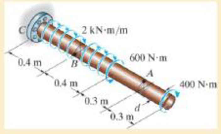
The 60-mm-diameter solid shaft is subjected to the distributed and concentrated torsional loadings shown. Determine the absolute maximum and minimum shear stresses on the shaft’s surface, and specify their locations, measured from the fixed end C.
Expert Solution & Answer
Want to see the full answer?
Check out a sample textbook solution
Students have asked these similar questions
The solid shaft is subjected to the distributed and concentrated torsional loadings shown. Determine the required diameter d of the shaft if the allowable shear stress for the material is tallow = 60 MPa.
The 60-mm-diameter solid shaft is subjected to the distributed and concentrated torsional loadings shown. Determine the shear stress at points A and B, and sketch the shear stress on volume elements located at these points.
A1 m long and 35 mm diameter aluminum shaft is to be replaced by a steel hollow shaft of the
same length and the same outside diameter. It is required to design the steel shaft to withstand
double the shear stress that of aluminum shaft. Determine the inside diameter of the stee I shaft.
Find the values of the shear stresses on each shaft if a torque of 3 kN.m is applied to both of
d=20mm
them.
Chapter 5 Solutions
Mechanics of Materials
Ch. 5.3 - The solid circular shaft is subjected to an...Ch. 5.3 - The hollow circular shaft is subjected to an...Ch. 5.3 - The shaft is hollow from A to B and solid from B...Ch. 5.3 - Determine the maximum shear stress in the...Ch. 5.3 - Determine the maximum shear stress in the shaft at...Ch. 5.3 - Determine the shear stress a: point A on the...Ch. 5.3 - The solid 50-mm-diameter shaft is subjected to the...Ch. 5.3 - The gear motor can develop 3 hp when it turns at...Ch. 5.3 - The solid shaft of radius r is subjected to a...Ch. 5.3 - The solid shaft of radius r is subjected to a...
Ch. 5.3 - Prob. 3PCh. 5.3 - The copper pipe has an outer diameter of 40 mm and...Ch. 5.3 - The copper pipe has an outer diameter of 2.50 in....Ch. 5.3 - The link acts as part of the elevator control for...Ch. 5.3 - The assembly consists of two sections of...Ch. 5.3 - A steel tube having an outer diameter of 2.5 in....Ch. 5.3 - The rod has a diameter of 1 in. and a weight of 10...Ch. 5.3 - The rod has a diameter of 1 in. and a weight of 15...Ch. 5.3 - Prob. 20PCh. 5.3 - The 60-mm-diameter solid shaft is subjected to the...Ch. 5.3 - The 60-mm-diameter solid shaft is subjected to the...Ch. 5.3 - The solid shaft is subjected to the distributed...Ch. 5.3 - If the tube is made from a material having an...Ch. 5.3 - Prob. 29PCh. 5.3 - The motor delivers 50 hp while turning at a...Ch. 5.3 - The solid steel shaft AC has a diameter of 25 mm...Ch. 5.3 - Prob. 35PCh. 5.4 - The 60 mm-diameter steel shaft is subjected to the...Ch. 5.4 - Prob. 10FPCh. 5.4 - The hollow 6061-T6 aluminum shaft has an outer and...Ch. 5.4 - A series of gears are mounted on the...Ch. 5.4 - The 80-mm-diameter shaft is made of steel. If it...Ch. 5.4 - The 80-mm-diameter shaft is made of steel. If it...Ch. 5.4 - The propellers of a ship are connected to an A-36...Ch. 5.4 - Show that the maximum shear strain in the shaft is...Ch. 5.4 - Determine the angle of twist of end B with respect...Ch. 5.4 - Determine the maximum allowable torque T. Also,...Ch. 5.4 - If the allowable shear stress is allow = 80 MPa,...Ch. 5.4 - Determine the angle of twist of the end A.Ch. 5.4 - The hydrofoil boat has an A992 steel propeller...Ch. 5.4 - Also, calculate the absolute maximum shear stress...Ch. 5.4 - If a torque of T = 50 N m is applied to the bolt...Ch. 5.4 - If a torque of T= 50N m is applied to the bolt...Ch. 5.4 - If the motor delivers 4 MW of power to the shaft...Ch. 5.4 - Determine the angle of twist at the free end A of...Ch. 5.5 - Gst = 75 GPa.Ch. 5.5 - The shaft is made of L2 tool steel, has a diameter...Ch. 5.5 - Each has a diameter of 25 mm and they are...Ch. 5.5 - Each has a diameter of 25 mm and they are...Ch. 5.5 - It is fixed at its ends and subjected to a torque...Ch. 5.5 - 5–89. Determine the absolute maximum shear stress...Ch. 5.7 - If the yield stress for brass is Y = 205 MPa,...Ch. 5.7 - By what percentage is the shaft of circular cross...Ch. 5.7 - Prob. 97PCh. 5.7 - Also, find the angle of twist of end B. The shaft...Ch. 5.7 - Also, find the corresponding angle of twist at end...Ch. 5.7 - Prob. 110PCh. 5.7 - Determine the average shear stress in the tube if...Ch. 5.7 - By what percentage is the torsional strength...Ch. 5.7 - Prob. 114PCh. 5.7 - Prob. 115PCh. 5.7 - Prob. 119PCh. 5.10 - Prob. 121PCh. 5.10 - If the radius of the fillet weld connecting the...Ch. 5.10 - Prob. 125PCh. 5.10 - Determine the radius of the elastic core produced...Ch. 5.10 - Prob. 128PCh. 5.10 - Determine the torque T needed to form an elastic...Ch. 5.10 - Determine the torque applied to the shaft.Ch. 5.10 - Prob. 131PCh. 5.10 - Determine the ratio of the plastic torque Tp to...Ch. 5.10 - Determine the applied torque T, which subjects the...Ch. 5.10 - Determine the radius of its elastic core if it is...Ch. 5.10 - Plot the shear-stress distribution acting along a...Ch. 5.10 - If the material obeys a shear stress-strain...Ch. 5.10 - It is made of an elastic perfectly plastic...Ch. 5.10 - Prob. 139PCh. 5.10 - Prob. 140PCh. 5.10 - Prob. 142PCh. 5.10 - Prob. 143PCh. 5 - The shaft is made of A992 steel and has an...Ch. 5 - The shaft is made of A992 steel and has an...Ch. 5 - Determine the shear stress at the mean radius p =...Ch. 5 - If the thickness of its 2014-T6-aluminum skin is...Ch. 5 - Determine which shaft geometry will resist the...Ch. 5 - If couple forces P = 3 kip are applied to the...Ch. 5 - If the allowable shear stress for the aluminum is...Ch. 5 - Determine the angle of twist of its end A if it is...Ch. 5 - This motion is caused by the unequal belt tensions...
Knowledge Booster


Learn more about
Need a deep-dive on the concept behind this application? Look no further. Learn more about this topic, mechanical-engineering and related others by exploring similar questions and additional content below.Similar questions
- Determine the absolute maximum shear stress in the shaft of Problemarrow_forwardA steel core is bonded firmly to the copper tube (shell) to form the shaft shown. The length of the shaft is 450 mm and the end A is fixed to the wall. Take the shear modulus of steel and copper as 76 GPa and 38 GPa, respectively. The diameter of the core is 60 mm and the outer diameter of the shaft is 100 mm. Determine the maximum external torque (Tmax) so that the absolute maximum shear stress for any point H on the surface of the copper shell does not exceed 50 MPa. 450 mm A 100 mm 60 mm В Tmax =? kN · marrow_forwardThe following shaft is free at A and connected to a fixed support at C. The shaft has a solid circular cross section with radius equal to 25 mm. given the two external forces at section A: (a) Determine the internal loading components at section B. (b) Determine the combined shear stress at point P located on top of section B. (c) Determine the combined normal stress at point P.arrow_forward
- The solid shaft is subjected to the distributed and concentrated torsional loadings shown. Determine the required diameter d of the shaft to the nearest mm if the allowable shear stress for the material is Tallow = 80 MPa. 2 kN m/m 1.5 m 1200 N-m B. 0,8 marrow_forwardThe electric motor exerts a torque of 800 N- m on the steel shaft ABCD when it is rotating at a constant speed. The angle of twist between A and D is limited to 1.50 degree. Use maximum shear = 60 MPa and modulus of rigidity = 77 GPa. Solve its torque for each shaft AB and BC. And determine the diameter of the Shaft based on strength. 300 N.m 500 N.m 0.4 m 0.6 m 0.3 marrow_forwardplease indicate the given and illustrationThe handwheel shown consists of the shaft, flange, and handle. A force P = 1 kN is applied to the handle as shown. The dimensions a and b are 110 mm and 220 mm respectively. If the diameter of the shaft is 24 mm, determine the maximum normal and shearing stress in the shaft.arrow_forward
- The hollow circular shaft is subjected to the torque of 4 kN # m. Determine the principal stresses at a point on the surface of the shaft.arrow_forwardThe 150-mm-diameter shaft is supported by a smooth journal bearing at E and a smooth thrust bearing at F. Determine the maximum shear stress developed in the shaft.arrow_forwardFor a given maximum average shear stress, determine the factor by which the torque-carrying capacity is increased if the half-circular section is reversed from the dashed-line position to the section shown. The tube is 0.1 in. thick.arrow_forward
- The hollow shaft has the cross section shown and is made of an elastic perfectly plastic material having a yield shear stress of tY . Determine the ratio of the plastic torque Tp to the maximum elastic torque TY.arrow_forwardDetermine the value of the maximum shear stress and the maximum normal stress produced in the structure shown, based on the cross section.arrow_forward4. The shaft below is hollow from A to B and solid from B to C. Determine the maximum shear stress in the shaft. The shaft has an outer diameter of 80mm and the thickness of the wall of the hollow segment is 10mm. Please note there are two different formula for solid and hollow shaft. 4 kN-m 2 kN-marrow_forward
arrow_back_ios
SEE MORE QUESTIONS
arrow_forward_ios
Recommended textbooks for you
 Elements Of ElectromagneticsMechanical EngineeringISBN:9780190698614Author:Sadiku, Matthew N. O.Publisher:Oxford University Press
 Mechanics of Materials (10th Edition)Mechanical EngineeringISBN:9780134319650Author:Russell C. HibbelerPublisher:PEARSON
 Thermodynamics: An Engineering ApproachMechanical EngineeringISBN:9781259822674Author:Yunus A. Cengel Dr., Michael A. BolesPublisher:McGraw-Hill Education
 Control Systems EngineeringMechanical EngineeringISBN:9781118170519Author:Norman S. NisePublisher:WILEY
 Mechanics of Materials (MindTap Course List)Mechanical EngineeringISBN:9781337093347Author:Barry J. Goodno, James M. GerePublisher:Cengage Learning
 Engineering Mechanics: StaticsMechanical EngineeringISBN:9781118807330Author:James L. Meriam, L. G. Kraige, J. N. BoltonPublisher:WILEY
Elements Of Electromagnetics
Mechanical Engineering
ISBN:9780190698614
Author:Sadiku, Matthew N. O.
Publisher:Oxford University Press
Mechanics of Materials (10th Edition)
Mechanical Engineering
ISBN:9780134319650
Author:Russell C. Hibbeler
Publisher:PEARSON
Thermodynamics: An Engineering Approach
Mechanical Engineering
ISBN:9781259822674
Author:Yunus A. Cengel Dr., Michael A. Boles
Publisher:McGraw-Hill Education
Control Systems Engineering
Mechanical Engineering
ISBN:9781118170519
Author:Norman S. Nise
Publisher:WILEY
Mechanics of Materials (MindTap Course List)
Mechanical Engineering
ISBN:9781337093347
Author:Barry J. Goodno, James M. Gere
Publisher:Cengage Learning
Engineering Mechanics: Statics
Mechanical Engineering
ISBN:9781118807330
Author:James L. Meriam, L. G. Kraige, J. N. Bolton
Publisher:WILEY
Understanding Torsion; Author: The Efficient Engineer;https://www.youtube.com/watch?v=1YTKedLQOa0;License: Standard YouTube License, CC-BY