
Concept explainers
Videos
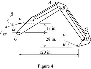
The motion of the backhoe bucket shown is controlled by the hydraulic cylinders AD, CG, and EF. As a result of an attempt to dislodge a portion of a slab, a 2-kip force P is exerted on the bucket teeth at J. Knowing that θ = 45°, determine the force exerted by each cylinder.
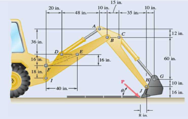
Fig. P6.157
The force exerted by each cylinder shown in figure
Answer to Problem 6.157P
The force exerted by the cylinder
Explanation of Solution
Take all vectors along the
Let P is the force exerted on the bucket at J.
The magnitude of force
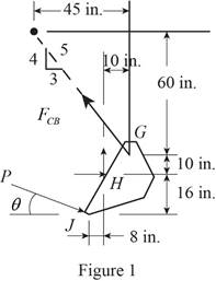
The free body diagram of the bucket is sketched below as figure 1.
Here,
Write the expression for the moment at
Here,
Above equation implies that net moment at any point is the sum of product of each force acting on the system and perpendicular distance of the force and the point.
The moment at
Thus, the complete expression of net anticlockwise moment
Here,
At equilibrium, the sum of the moment acting at
Write the expression for the total moment acting at
From figure 1 , write the expression for the
From figure 1 , write the expression for the
The free body diagram of the bucket and arm
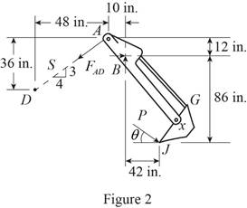
Here,
Write the expression for the moment at
Here,
Above equation implies that net moment at any point is the sum of product of each force acting on the system and perpendicular distance of the force and the point.
The moment at
Thus, the complete expression of net anticlockwise moment
Here,
At equilibrium, the sum of the moment acting at
Write the expression for the total moment acting at
From figure 2 , write the expression for the
Geometry of cylinder
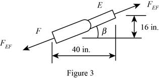
The free body diagram of the bucket and both arms is sketched below as figure 4.
Here,
Write the expression for the moment at
Here,
Above equation implies that net moment at any point is the sum of product of each force acting on the system and perpendicular distance of the force and the point.
The moment at
Thus, the complete expression of net anticlockwise moment
Here,
At equilibrium, the sum of the moment acting at
Write the expression for the total moment acting at
From figure 3 , write the expression for the
Calculation:
Substitute
The negative sign indicate that the cylinder undergoes compression.
Substitute
The negative sign indicate that the cylinder undergoes compression.
Rearrange the equation (X) to get

Substitute
The positive sign indicate that the cylinder
Therefore, the force exerted by the cylinder
Want to see more full solutions like this?
Chapter 6 Solutions
Vector Mechanics for Engineers: Statics


- 4.95 The linkage of the braking system consists of the pedal arm DAB, the connecting rod BC, and the hydraulic cylinder C. At what angle 0 will the force Q be four times greater than the force P applied to the pedal? Neglect friction and the weight of the linkage. 250 mm Fig. P4.95 100 mm -100 mmarrow_forward4.81 When activated by the force P, the gripper on a robotic arm is able to pick up objects by applying the gripping force F. Given that P = 120 N, calculate the gripping force for the position shown. 160 mm - 250 mm 52 mm- B m m. D m m. Fig. P4.81arrow_forward6.139 A hand-operated hydraulic cylinder has been designed for uhe where space is severely limited. Determine the magnitude of the force ca erted on the piston at D when two 90-lb forces are applied as shown. 90 lb -4 in.- - 9.2 in.- |c A 0.9 in.f 2.4 in. 0.9 in.1 2.4 in. В E 2 in. 90 lb Fig. P6.139arrow_forward
- In order to unscrew the tapped faucet A , a plumber uses two pipe wrenches as shown. By exerting a 40-lb force on each wrench at a distance of 10 in. from the axis of the pipe and in a direction perpendicular to the pipe and to the wrench, he prevents the pipe from rotating, and thus he avoids loosening or further tightening the joint between the pipe and the tapped elbow C . Determine (a) the angle 0 that the wrench at A should form with the vertical if elbow C is not to rotate about the vertical, (b) the force-couple system at C equivalent to the two 40-lb forces when this condition is satisfied.arrow_forwardThe L-shaped member ACB is supported by a pin and bracket at C and by an inextensible cord attached at A and B and passing over a frictionless pulley at D. The tension may be assumed to be the same in portions AD and BD of the cord. If the magnitudes of the forces applied at A and B are, respectively, P = 25 lb and Q = 0, determine (a) the tension in the cord, (b) the reaction at Carrow_forwardQ. 1: The man exerts a force P of magnitude 50 lb on the handles of the wheelbarrow. Knowing that resultant of forces, P, Q (the reaction at the wheel), and W (the weight of the wheelbarrow) is the force R= 10i lb, determine W. 30 Warrow_forward
- 25 mm 60 mm 85 mm D 75 mm 6.136 The tongs shown are used to apply a total upward force of 45 ky on a pipe cap. Determine the forces exerted at D and F on tong ADF. E F 90 mm Fig. P6.136arrow_forwardThe telescoping arm ABC of Prob. 6.93 can be lowered until end C is close to the ground, so that workers can easily board the platform.For the position when θ = -220°, determine (a) the force exerted at B by the single hydraulic cylinder BD, (b) the force exerted on the supporting carriage at A.arrow_forwardQ.4. Determine the force F required to hold the system in equilibrium if a torque M of 240 N-m is applied at point D in the counter-clockwise direction. Assume the weights of all members are negligible and that collar B freely moves along the horizontal rod with negligible friction. 160 mm 90 mm 180 mm B M 320 mm D 125 mm 300 mmarrow_forward
- The lid of a roof scuttle weighs 75 lb. It is hinged at corners A and B and maintained in the desired position by a rod CD pivoted at C; a pin at end D of the rod fits into one of several holes drilled in the edge of the lid. For α=50°, determine (a) the magnitude of the force exerted by rod CD, (b) the reactions at the hinges. Assume that the hinge at B does not exert any axial thrust.arrow_forwardThe uniform 10 kg rod AB is supported by a ball and socket joint at A and by the cord CG that is attached to the midpoint G of the rod. Knowing that the rod leans against a frictionless vertical wall at B and that the tension in the cord CG, TCG=52.1 N, determine the following a.) Which of the following best shows the equivalent force-couple set at point A of the tension at cord CG, TCG? Choices: a F= -36.8 N i + 24.5 N j - 27.6 N k M = -7.36 Nm i - 11.03 Nm j b F= -36.8 N i + 24.5 N j - 27.6 N k M = -7.36 Nm i - 29.4 Nm k c F= 36.8 N i - 24.5 N j + 27.6 N k M = 7.36 Nm i + 11.03 Nm j d F= 36.8 N i - 24.5 N j + 27.6 N k M = 7.36 Nm i + 29.4 Nm k b.) Which of the following moments is equal to zero? Choices: The moment of the tension in cord CG, TCG about point OThe moment of the tension in cord CG, TCG about point AThe moment of the tension in cord CG, TCG about point BThe moment of the tension in cord CG, TCG about axis ABarrow_forward6.142 A locking C-clamp is used to clamp two pieces of -in. steel plate. Determine the magnitude of the gripping forces produced when two 30-lb forces are applied as shown. -2.6 in.- -1.9 in. -1.3 in.- |30 lb A Bo + 0.85 in. 0.3 in. -2.6 in.- 30 lb 0.8 in. Fig. P6.142arrow_forward
 Elements Of ElectromagneticsMechanical EngineeringISBN:9780190698614Author:Sadiku, Matthew N. O.Publisher:Oxford University Press
 Mechanics of Materials (10th Edition)Mechanical EngineeringISBN:9780134319650Author:Russell C. HibbelerPublisher:PEARSON
 Thermodynamics: An Engineering ApproachMechanical EngineeringISBN:9781259822674Author:Yunus A. Cengel Dr., Michael A. BolesPublisher:McGraw-Hill Education
 Control Systems EngineeringMechanical EngineeringISBN:9781118170519Author:Norman S. NisePublisher:WILEY
 Mechanics of Materials (MindTap Course List)Mechanical EngineeringISBN:9781337093347Author:Barry J. Goodno, James M. GerePublisher:Cengage Learning
 Engineering Mechanics: StaticsMechanical EngineeringISBN:9781118807330Author:James L. Meriam, L. G. Kraige, J. N. BoltonPublisher:WILEY