
Mechanics of Materials
9th Edition
ISBN: 9780133254426
Author: Russell C. Hibbeler
Publisher: Prentice Hall
expand_more
expand_more
format_list_bulleted
Concept explainers
Videos
Textbook Question
Chapter 7.2, Problem 7.1PP
In each case, calculate the value of Q and t that are used in the shear formula for finding the shear stress at A. Also, show how the shear stress acts on a differential volume element located at point A.
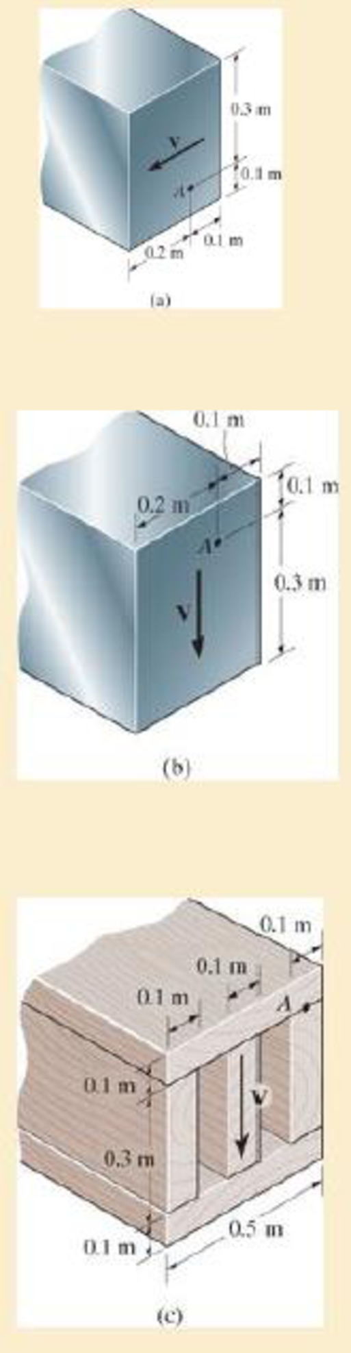
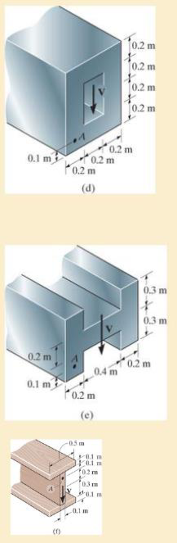
P7–1
Expert Solution & Answer

Learn your wayIncludes step-by-step video

schedule06:32
Students have asked these similar questions
1) Two wrenches are used to tighten the pipe. If P = 300 N is applied to each wrench, determine
the maximum torsional shear stress developed within regions AB and BC. The pipe has an outer
diameter of 25 mm and inner diameter of 20 mm. Sketch the shear stress distribution for both
cases.
250 mm
B
250 mm
The state of stress of an element is given.
Determine its principle plane by the
specialized formulas and Mohr's circle,
separately.
42 MPa
38 MPa
y
24 MPa
Use Mohr's Circle to determine the maximum shear stress on the element, also using Mohr's Circle determine the maximum normal stress on the element.
Chapter 7 Solutions
Mechanics of Materials
Ch. 7.2 - In each case, calculate the value of Q and t that...Ch. 7.2 - If the beam is subjected to a shear force of V =...Ch. 7.2 - Determine the shear stress at points A and B if...Ch. 7.2 - Determine the absolute maximum shear stress in the...Ch. 7.2 - If the beam is subjected to a shear force of V =20...Ch. 7.2 - If the beam is made from four plates and subjected...Ch. 7.2 - If the wide-flange beam is subjected to a shear of...Ch. 7.2 - If the wide-flange beam is subjected to a shear of...Ch. 7.2 - If the wide-flange beam is subjected to a shear of...Ch. 7.2 - Prob. 7.4P
Ch. 7.2 - Prob. 7.5PCh. 7.2 - The wood beam has an allowable shear stress of...Ch. 7.2 - The shaft is supported by a thrust bearing at A...Ch. 7.2 - The shaft is supported by a thrust bearing at A...Ch. 7.2 - Determine the largest shear force V that the...Ch. 7.2 - If the applied shear force V = 18 kip, determine...Ch. 7.2 - The overhang beam is subjected to the uniform...Ch. 7.2 - *7-12. The beam has a rectangular cross section...Ch. 7.2 - Determine the maximum shear stress in the strut if...Ch. 7.2 - Determine the maximum shear force V that the strut...Ch. 7.2 - 7-15. The strut is subjected to a vertical shear...Ch. 7.2 - Prob. 7.16PCh. 7.2 - If the beam is subjected to a shear of V=15 kN,...Ch. 7.2 - If the wide-flange beam is subjected to a shear of...Ch. 7.2 - If the wide-flange beam is subjected to a shear of...Ch. 7.2 - Prob. 7.20PCh. 7.2 - If the beam is made from wood having an allowable...Ch. 7.2 - Determine the shear stress at point B on the web...Ch. 7.2 - Determine the maximum shear stress acting at...Ch. 7.2 - Prob. 7.24PCh. 7.2 - 7-25. Determine the maximum shear stress in the...Ch. 7.2 - 7-26. The beam has a square cross section and is...Ch. 7.2 - The beam is slit longitudinally along both sides....Ch. 7.2 - The beam is to be cut longitudinally along both...Ch. 7.2 - The beam has a rectangular cross section and is...Ch. 7.2 - The beam in Fig.6-48f is subjected to a fully...Ch. 7.3 - The two identical boards are bolted together to...Ch. 7.3 - Two identical 20-mm-thick plates are bolted to the...Ch. 7.3 - The boards are bolted together to form the...Ch. 7.3 - The boards are bolted together to form the...Ch. 7.3 - Prob. 7.32PCh. 7.3 - Prob. 7.33PCh. 7.3 - Prob. 7.34PCh. 7.3 - Prob. 7.35PCh. 7.3 - Prob. 7.36PCh. 7.3 - Prob. 7.37PCh. 7.3 - Prob. 7.38PCh. 7.3 - A beam is constructed from three boards bolted...Ch. 7.3 - The simply supported beam is built up from three...Ch. 7.3 - The simply supported beam is built up from three...Ch. 7.3 - The T-beam is constructed as shown. If each nail...Ch. 7.3 - Prob. 7.43PCh. 7.3 - Prob. 7.44PCh. 7.3 - Prob. 7.45PCh. 7.3 - 7–46. The beam is subjected to a shear of V = 800...Ch. 7.3 - The beam is made from four boards nailed together...Ch. 7.3 - The beam is made from three polystyrene strips...Ch. 7.5 - A shear force of V=300 kN is applied to the box...Ch. 7.5 - A shear force of V=450 kN is applied to the box...Ch. 7.5 - A shear force of V = 18 kN is applied to the box...Ch. 7.5 - A shear force of V = 18 kN is applied to the box...Ch. 7.5 - The aluminum strut is 10 mm thick and has the...Ch. 7.5 - The aluminum strut is 10 mm thick and has the...Ch. 7.5 - Prob. 7.56PCh. 7.5 - Prob. 7.57PCh. 7.5 - Prob. 7.58PCh. 7.5 - Prob. 7.59PCh. 7.5 - The built-up beam is formed by welding together...Ch. 7.5 - The assembly is subjected to a vertical shear of V...Ch. 7.5 - 7–62. Determine the shear-stress variation over...Ch. 7.5 - 7–63. Determine the location e of the shear...Ch. 7.5 - Determine the location e of the shear center,...Ch. 7.5 - The beam supports a vertical shear of V=7 kip....Ch. 7.5 - The stiffened beam is constructed from plates...Ch. 7.5 - The pipe is subjected to a shear force of V=8 kip....Ch. 7.5 - *7–68. A thin plate of thickness t is bent to form...Ch. 7.5 - A thin plate of thickness t is bent to form the...Ch. 7.5 - 7–70. Determine the location e of the shear...Ch. 7 - The beam is fabricated from four boards nailed...Ch. 7 - The T-beam is subjected to a shear of V = 150 kN....Ch. 7 - The member is subject to a shear force of V = 2...Ch. 7 - Determine the shear stress at points B and C on...Ch. 7 - Determine the maximum shear stress acting at...
Additional Engineering Textbook Solutions
Find more solutions based on key concepts
What parts are included in the vehicle chassis?
Automotive Technology: Principles, Diagnosis, And Service (6th Edition) (halderman Automotive Series)
1.1 What is the difference between an atom and a molecule? A molecule and a crystal?
Manufacturing Engineering & Technology
Represent each of the following with SI units having an appropriate prefix: (a) 8653 ms, (b) 8368 N, (c) 0.893 ...
Statics and Mechanics of Materials (5th Edition)
Determine the angle for equilibrium and the force in cord AB.
INTERNATIONAL EDITION---Engineering Mechanics: Statics, 14th edition (SI unit)
The truss is supported by a pin at A and a roller at B. Determine the support reactions. Prob. F5-3
Engineering Mechanics: Statics
Comprehension Check 8-15
You push an automobile with a constant force of 20 pound-force [lbf] until 1,500 joule...
Thinking Like an Engineer: An Active Learning Approach (4th Edition)
Knowledge Booster


Learn more about
Need a deep-dive on the concept behind this application? Look no further. Learn more about this topic, mechanical-engineering and related others by exploring similar questions and additional content below.Similar questions
- The steel step shaft has an allowable shear stress of Fallow 9 MPa. If the transition between the cross-sections has a radius r-4 mm, determine the maximum torque T that can be applied. Take K-1.25. 20 mm 72 N.m T 50 mm 20 mm 7/2 The maximum torque T that can be applied is. Note: Please enter your answer with three significant digits after the decimal point. Take the torque as positive since the problem does not have multiple sections before the step.arrow_forwardUse Mohr’s circle to determine the normal stress and shear stress acting on the inclined plane AB.arrow_forwardDetermine also the maximum shear stress and shear stress angle.arrow_forward
- Determine the normal stress and shear stress at a point distant from hP from the bottom surface of the depicted cross, also determine the maximum normal stress and maximum shear stress in the cross section. t=10 mm w= 150 mm h=180 mm V= 5 kN M= 3 kN.m hP= 145 mmarrow_forwardA rectangular block of dimensions 75 mm x 75 mm x 150 mm is subjected to a shear stress of 5 MPa alongits square face. Determine the shear strain and shear deformation in the block given a shear modulus of 80GPa.arrow_forwardThe wide-flange beam is subjected to the 50-kN force. Determine the principal stresses in the beam at point A located on the web at the bottom of the upper flange. Although it is not very accurate, use the shear formula to calculate the shear stress. A B₂ ➜ 10 mm- B 200 mm 12 mm 250 mm 12 mm -3 m 50 kNarrow_forward
- The bar has a 100 mm by 15 mm rectangular cross section. The allowable normal and shear stresses on inclined 66° surface a – a must be limited to 50 MPa and 35 MPa, respectively. Determine the 100 mm magnitude of the maximum axial force P that can be applied to the bar, and determine the actual normal and shear Try one stresses acting on inclined plane a – a.arrow_forwardThe plate has a thickness of 20 mm and the force P = 3 kN acts along the centerline of this thickness such that d = 150 mm. Plot the distribution of normal stress acting along section a–a.arrow_forwardDetermine the maximum shear stress If maximum principal stress=50 MPa , Minimum principal Stress=20 Mpaarrow_forward
- Consider the given state of stress. Take X = 35 MPa and Y = 50 MPa Determine the orientation of the planes of maximum in-plane shearing stress in the first and third quadrantsarrow_forwardThe thin-walled pipe has an inner diameter of 1.2 cm and a thickness of 0.06 cm. If it is subjected to an internal pressure of 4 MPa and the axial tension and torsional loadings shown, determine the principal stress and the absolute maximum shear stress at a point on the surface of the pipe. (15' in total) 2000 N 2000 N 8 N-m 8 N-m 1.2 cm 0.06 cmarrow_forwardThe grains of wood in the board make an angle of 20 with the horizontal as shown. Using Mohr's circle, determine the normal and shear stresses that act perpendicular and parallel to the grains if the board is subjected to an axial load of P = 260 N. Determine the normal stress and shear stress. -300 mm- 20⁰ 25 mm- 60 mm Parrow_forward
arrow_back_ios
SEE MORE QUESTIONS
arrow_forward_ios
Recommended textbooks for you
 Elements Of ElectromagneticsMechanical EngineeringISBN:9780190698614Author:Sadiku, Matthew N. O.Publisher:Oxford University Press
 Mechanics of Materials (10th Edition)Mechanical EngineeringISBN:9780134319650Author:Russell C. HibbelerPublisher:PEARSON
 Thermodynamics: An Engineering ApproachMechanical EngineeringISBN:9781259822674Author:Yunus A. Cengel Dr., Michael A. BolesPublisher:McGraw-Hill Education
 Control Systems EngineeringMechanical EngineeringISBN:9781118170519Author:Norman S. NisePublisher:WILEY
 Mechanics of Materials (MindTap Course List)Mechanical EngineeringISBN:9781337093347Author:Barry J. Goodno, James M. GerePublisher:Cengage Learning
 Engineering Mechanics: StaticsMechanical EngineeringISBN:9781118807330Author:James L. Meriam, L. G. Kraige, J. N. BoltonPublisher:WILEY
Elements Of Electromagnetics
Mechanical Engineering
ISBN:9780190698614
Author:Sadiku, Matthew N. O.
Publisher:Oxford University Press
Mechanics of Materials (10th Edition)
Mechanical Engineering
ISBN:9780134319650
Author:Russell C. Hibbeler
Publisher:PEARSON
Thermodynamics: An Engineering Approach
Mechanical Engineering
ISBN:9781259822674
Author:Yunus A. Cengel Dr., Michael A. Boles
Publisher:McGraw-Hill Education
Control Systems Engineering
Mechanical Engineering
ISBN:9781118170519
Author:Norman S. Nise
Publisher:WILEY
Mechanics of Materials (MindTap Course List)
Mechanical Engineering
ISBN:9781337093347
Author:Barry J. Goodno, James M. Gere
Publisher:Cengage Learning
Engineering Mechanics: Statics
Mechanical Engineering
ISBN:9781118807330
Author:James L. Meriam, L. G. Kraige, J. N. Bolton
Publisher:WILEY
Everything About COMBINED LOADING in 10 Minutes! Mechanics of Materials; Author: Less Boring Lectures;https://www.youtube.com/watch?v=N-PlI900hSg;License: Standard youtube license