
Steel Design (Activate Learning with these NEW titles from Engineering!)
6th Edition
ISBN: 9781337094740
Author: Segui, William T.
Publisher: Cengage Learning
expand_more
expand_more
format_list_bulleted
Concept explainers
Question
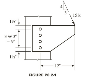
Chapter 8, Problem 8.2.1P
To determine
The maximum bolt shear force in the given bracket connection by using an elastic analysis.
Expert Solution & Answer
Answer to Problem 8.2.1P
Explanation of Solution
Given:
Calculation:
Determine the direct shear components:
Eccentricity:
Top bolt is critical.
Conclusion:
The maximum bolt shear force in the given bracket connection is
Want to see more full solutions like this?
Subscribe now to access step-by-step solutions to millions of textbook problems written by subject matter experts!
Students have asked these similar questions
The frame is subjected to the load of 200 lb. Determine the average shear
stress in the bolt at A. The bolt has a diameter of 0.25 inches and in single
shear.
A
2ft
B
.5ft
-1.5ft-> 200lb
The bracket shown carries an eccentric load P at an eccentricity e=400mm. The column and bracket are A36 steel.
Diameter of bolt is 22mm in standard holes. Assume that the column flange and the bracket are thick enough that
single shear in the bolts will control. Shear capacity of one bolt is 45KN.
a. Determine the polar moment of Inertia of the bolt group
b. Determine the maximum load P that the bolted connection can support.
C. Determine the direct load carried by the most critical bolt
d. Determine the load due to moment carried by the most critical bolt.
e = 400 mm
75
751
15
75
75
70 70
A rigid bar AC is supported pinned supported at A and bar DB at B. See
typical bolt connection detail. A concentrated weight, denoted as W is
attached at the end of the rigid bar.
L1 = 2.6 m
L2 = 2.1 m
H= 1.2 m
W= 14 KN
What is the required diameter of the bolt (in mm) at connection B given
the allowable shearing stress to be 40 MPa ? Consider single shear.
L1
L2
A
B
C
H
D
इस
W
CONNECTION AT B
Chapter 8 Solutions
Steel Design (Activate Learning with these NEW titles from Engineering!)
Ch. 8 - Prob. 8.2.1PCh. 8 - Prob. 8.2.2PCh. 8 - A plate is used as a bracket and is attached to a...Ch. 8 - Prob. 8.2.4PCh. 8 - Prob. 8.2.5PCh. 8 - Prob. 8.2.6PCh. 8 - Prob. 8.2.7PCh. 8 - Prob. 8.2.8PCh. 8 - Prob. 8.2.9PCh. 8 - Prob. 8.2.10P
Ch. 8 - Prob. 8.2.11PCh. 8 - Prob. 8.2.12PCh. 8 - Prob. 8.2.13PCh. 8 - Prob. 8.3.1PCh. 8 - Prob. 8.3.2PCh. 8 - Prob. 8.3.3PCh. 8 - Prob. 8.3.4PCh. 8 - Prob. 8.3.5PCh. 8 - Prob. 8.3.6PCh. 8 - Prob. 8.3.7PCh. 8 - Prob. 8.3.8PCh. 8 - Prob. 8.3.9PCh. 8 - Prob. 8.3.10PCh. 8 - Use an elastic analysis and determine the maximum...Ch. 8 - Use an elastic analysis and determine the maximum...Ch. 8 - Use an elastic analysis and determine the maximum...Ch. 8 - Prob. 8.4.4PCh. 8 - Prob. 8.4.5PCh. 8 - Prob. 8.4.6PCh. 8 - Use an elastic analysis and compute the extra load...Ch. 8 - Use an elastic analysis and compute the extra load...Ch. 8 - Prob. 8.4.9PCh. 8 - Prob. 8.4.10PCh. 8 - Prob. 8.4.11PCh. 8 - Prob. 8.4.12PCh. 8 - Prob. 8.4.13PCh. 8 - Prob. 8.4.14PCh. 8 - Prob. 8.4.15PCh. 8 - Prob. 8.4.16PCh. 8 - Prob. 8.4.17PCh. 8 - Prob. 8.4.18PCh. 8 - a. Use LRFD and design a welded connection for the...Ch. 8 - Prob. 8.4.20PCh. 8 - Prob. 8.5.1PCh. 8 - Prob. 8.5.2PCh. 8 - Prob. 8.5.3PCh. 8 - Prob. 8.5.4PCh. 8 - Prob. 8.5.5PCh. 8 - Prob. 8.6.1PCh. 8 - Prob. 8.6.2PCh. 8 - Prob. 8.6.3PCh. 8 - Prob. 8.6.4PCh. 8 - Prob. 8.7.1PCh. 8 - Prob. 8.7.2PCh. 8 - Prob. 8.7.3PCh. 8 - Prob. 8.8.1PCh. 8 - Prob. 8.8.2PCh. 8 - Prob. 8.8.3PCh. 8 - Prob. 8.8.4P
Knowledge Booster


Learn more about
Need a deep-dive on the concept behind this application? Look no further. Learn more about this topic, civil-engineering and related others by exploring similar questions and additional content below.Similar questions
- The frame is subjected to the load of 200 lb. Determine the average shear stress in the bolt at A. The bolt has a diameter of 0.25 inches and in single shear. ID 2 ft 1.5 ft 200 lb B 0.5 ftarrow_forwardAn 8 mm diameter pin is used at A, and 12 mm diameter pins are used at B and D. Knowing that the ultimate shearing stress is 100 MPa at all connections and that the ultimate normal stress is 250 MPa in each of the two links joining B and D, determine the allowable load P. Top view 200 mm +180 mm 12 mm 8 mm B B A B 20 mm +8 mm 8 mm OD 12 mm -- - Front view Side viewarrow_forwardSITUATION 1 An eccentrically loaded bolted connection is shown. Diameter of A 325 bolts in standard holes is 19mm. The applied load is 45kN a. Determine the polar moment of Inertia of the group bolts b. Determine the torsional force on the critical bolt c. Determine the shearing stress of critical bolt. Le = 250 mmP = 45 kN 100 100 '15 75arrow_forward
- SOLVE FOR THE FORCE IN MEMBERS AB, AC, BC, CD, BD, BE, DE, DF & EF. SHOW SOLUTIONS CLEARLY USING METHOD OF JOINTS AND WRITE WELL ALSO SEE LINK UNDER WEEK7 0.8m 2.4m -6KN MEMBER AB AC BC CD BD BE 2m ED DF EF 1m 8KN Av REACTION hinge) EX REACTION @roller) 3m SUMMARY OF RESULTS FORCE 1m 10KN 2.4m 3KN NATURE(I or C)arrow_forward*12-32. The double T-beam is fabricated by welding the three plates together as shown. Determine the shear stress in the weld necessary to support a shear farce af V = 80 kN 20 mm 150 mm So mm 75 mm So mm 20 mm 20 mmarrow_forwardWhere is/are the location(s) of the maximum transverese shear stress? A simple I-beam is loaded as shown. 20 mm P KN PKN PKN Į Į -C B с D L/4 m L/4 m Midspan at point C Roller at E at the NA Section B at the top fiber Pin A at point C Midspan at point D Roller E at point D L/4 m L/4 m OE 20 mm 20 mm- 250 mm 150 mm 150 mm Aarrow_forward
- The figure shows a roof truss and the detail of the connection at joint G. Members BG and CG are angle sections with the thicknesses shown in the The working stresses are 70 MPa for shear in the rivets and 140 MPa for bearing stress due to the rivets. How many 25-mm-diameter rivets are required to fasten the following members to the gusset plate: (a) BG; and (b) CG?arrow_forwardFor the connection shown, determine the shear stress in the 22-mm diameter bolt for an applied load of P= 90 kN. Parrow_forwardthe connection consists of a plate connected to another plate by five 25-mm diameter rivets. it carries a load P = 80 kN. Determine the shear stress on the bolt due to the effect of force alone.arrow_forward
- 2. Member BC in the truss below is a 300 mm wide, 10 mm thick steel plate attached to two other 12 mm plates at Joint C by three 24 mm diameter A325N bolts. The plate is A50. Determine the safe load Pu using ASD that the truss can resist according to the capacity of the connection. LS 15 WR + 14 DATE ON ON Mmm 70 m 40 mmarrow_forwardThe bearing-type-in. A325 bolts of the connection of Fig. have an al- lowable strength = (0.6)(30) = 18 k. Locate the instantaneous center of rota- tion of the connection, using the trial-and-error procedure, and determine the value of P. O O -5 in. F O +3 in. O P 6 in.arrow_forwardAn 8 mm diameter pin is used at A, and 12 mm diameter pins are used at B and D. Knowing that the ultimate shearing stress is 100 MPa at all connections and that the ultimate normal stress is 250 MPa in each of the two links joining B and D, determine the allowable load P. Top view -200 mm--180 mm --12 mm 8 mm - 20 mm 8 mm 8 mm 12 mm - - Front view Side viewarrow_forward
arrow_back_ios
SEE MORE QUESTIONS
arrow_forward_ios
Recommended textbooks for you

 Structural Analysis (10th Edition)Civil EngineeringISBN:9780134610672Author:Russell C. HibbelerPublisher:PEARSON
 Principles of Foundation Engineering (MindTap Cou...Civil EngineeringISBN:9781337705028Author:Braja M. Das, Nagaratnam SivakuganPublisher:Cengage Learning
 Fundamentals of Structural AnalysisCivil EngineeringISBN:9780073398006Author:Kenneth M. Leet Emeritus, Chia-Ming Uang, Joel LanningPublisher:McGraw-Hill Education
 Traffic and Highway EngineeringCivil EngineeringISBN:9781305156241Author:Garber, Nicholas J.Publisher:Cengage Learning
Structural Analysis (10th Edition)
Civil Engineering
ISBN:9780134610672
Author:Russell C. Hibbeler
Publisher:PEARSON
Principles of Foundation Engineering (MindTap Cou...
Civil Engineering
ISBN:9781337705028
Author:Braja M. Das, Nagaratnam Sivakugan
Publisher:Cengage Learning
Fundamentals of Structural Analysis
Civil Engineering
ISBN:9780073398006
Author:Kenneth M. Leet Emeritus, Chia-Ming Uang, Joel Lanning
Publisher:McGraw-Hill Education
Traffic and Highway Engineering
Civil Engineering
ISBN:9781305156241
Author:Garber, Nicholas J.
Publisher:Cengage Learning