
Mechanics of Materials (MindTap Course List)
9th Edition
ISBN: 9781337093347
Author: Barry J. Goodno, James M. Gere
Publisher: Cengage Learning
expand_more
expand_more
format_list_bulleted
Concept explainers
Videos
Textbook Question
Chapter 8, Problem 8.5.28P
A crank arm consists of a solid segment of length bxand diameter rf, a segment of length bltand a segment of length byas shown in the figure. Two loads P act as shown: one parallel to — vand another parallel to —y. Each load P equals 1.2 kN. The crankshaft dimensions are A] = 75 mm, fr> = 125 mm, and b3= 35 mm. The diameter of the upper shaft isd = 22 mm,
(a) Determine the maximum tensile, compressive, and shear stresses at point A, which is located on the surface of the shaft at the z axis.
(b) Determine the maximum tensile, compressive, and shear stresses at point B, which is located on the surface of the shaft at the y axis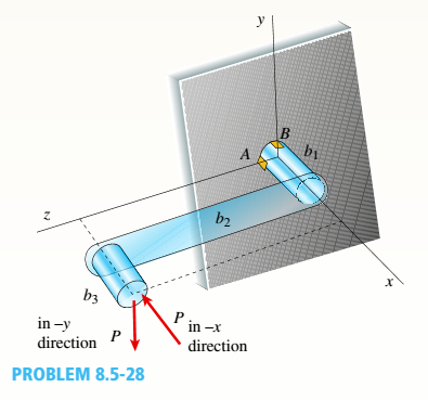
Expert Solution & Answer

Trending nowThis is a popular solution!

Students have asked these similar questions
L length of the adjustable wrench in the figure; Choose a number from 152 to 252 mm that does
not end with a zero. F force also; Choose from 122 to 292N as a non-zero number. Find the
torque and direction of the wrench applied to the bolt. ? (Note: Fill in the table.)
EN
L = 155 mm
15%
F = 215N
L mm
a) Momentum = ?
b) Direction = ?
30 mm
Question 5
A crank arm consists of a sold segment of length bi and diameter d, a segment of length b2,
and a segment of length b3 as shown n Figure Q5 Two loads P act as shown one parallel to
-x and another parallel to -y Each load P equals 1 2 kN The crankshaft dimensions are b
75 mm, b2 125 mm, and b3 = 35 mm. The diameter of the upper shaft is d 22 mm
Determine the maxımum tensile, compressive, and shear stresses at point A, which is located
on the surface of the shaft at the z axis
Tr
Hint Shear stress due to Torsion is T
Tis the torque on the shaft,
Ip
r is the shaft radus and In is the
16V
4V
Shear stress due to shear fore Vs T
3A
polar moment of inerta gven by
3πα2
32
B
b
b3
in-x directon
P in -y directon
Figure Q5
Prob. # 1] Figure below shows a crank loaded by a force F = 300 lb that causes twisting and
bending of a 3/4-inch-diameter shaft fixed to a support at the origin of the reference system. In
actuality, the support may be an inertia, but for the purposes of a stress analysis consider this
as a statics problem.
a) Draw separate free-body diagrams of the shaft AB and the arm BC, and compute the
values of all forces, moments, and torques. Label the directions of the coordinate axes
on these diagrams.
b) Compute the torsional stress and the bending stress in the arm BC and indicate where
these act.
c) Locate a stress element on the top surface of the shaft at A, and calculate all the stress
components that act upon this element.
d) Determine the maximum and minimum principal stresses at point A, and the angle of
inclination of the planes on which the principal stresses act.
e) Determine maximum shear stress at point A and the angle of inclination of the element
on which the maximum shear…
Chapter 8 Solutions
Mechanics of Materials (MindTap Course List)
Ch. 8 - A spherical balloon is filled with a gas. The...Ch. 8 - A spherical balloon with an outer diameter of 500...Ch. 8 - A large spherical tank (see figure) contains gas...Ch. 8 - Solve the preceding problem if the internal...Ch. 8 - A hemispherical window (or viewport) in a...Ch. 8 - A rubber ball (sec figure) is inflated to a...Ch. 8 - (a) Solve part (a) of the preceding problem if the...Ch. 8 - A spherical steel pressure vessel (diameter 500...Ch. 8 - A spherical tank of diameter 48 in. and wall...Ch. 8 - Solve the preceding problem for the following...
Ch. 8 - A spherical stainless-steel tank having a diameter...Ch. 8 - Solve the preceding problem if the diameter is 480...Ch. 8 - : A hollow, pressurized sphere having a radius r =...Ch. 8 - A fire extinguisher tank is designed for an...Ch. 8 - Prob. 8.3.2PCh. 8 - A scuba t a n k (see fig ure) i s bci ng d e...Ch. 8 - A tall standpipc with an open top (see figure) has...Ch. 8 - An inflatable structure used by a traveling circus...Ch. 8 - A thin-walled cylindrical pressure vessel of a...Ch. 8 - A strain gage is installed in the longitudinal...Ch. 8 - A circular cylindrical steel tank (see figure)...Ch. 8 - A cylinder filled with oil is under pressure from...Ch. 8 - Solve the preceding problem if F =90 mm, F = 42...Ch. 8 - A standpipe in a water-supply system (see figure)...Ch. 8 - A cylindrical tank with hemispherical heads is...Ch. 8 - : A cylindrical tank with diameter d = 18 in, is...Ch. 8 - A pressurized steel tank is constructed with a...Ch. 8 - Solve the preceding problem for a welded Tank with...Ch. 8 - A wood beam with a cross section 4 x 6 in. is...Ch. 8 - Prob. 8.4.2PCh. 8 - A simply supported beam is subjected to two point...Ch. 8 - A cantilever beam with a width h = 100 mm and...Ch. 8 - A beam with a width h = 6 in. and depth h = 8 in....Ch. 8 - Beam ABC with an overhang BC is subjected to a...Ch. 8 - A cantilever beam(Z, = 6 ft) with a rectangular...Ch. 8 - Solve the preceding problem for the following...Ch. 8 - A simple beam with a rectangular cross section...Ch. 8 - An overhanging beam ABC has a guided support at A,...Ch. 8 - Solve the preceding problem if the stress and...Ch. 8 - A cantilever wood beam with a width b = 100 mm and...Ch. 8 - . A cantilever beam (width b = 3 in. and depth h =...Ch. 8 - A beam with a wide-flange cross section (see...Ch. 8 - A beam with a wide-flange cross section (see...Ch. 8 - A W 200 x 41.7 wide-flange beam (see Table F-l(b),...Ch. 8 - A W 12 x 35 steel beam is fixed at A. The beam has...Ch. 8 - A W 360 x 79 steel beam is fixed at A. The beam...Ch. 8 - A W 12 X 14 wide-flange beam (see Table F-l(a),...Ch. 8 - A cantilever beam with a T-section is loaded by an...Ch. 8 - Beam A BCD has a sliding support at A, roller...Ch. 8 - , Solve the preceding problem using the numerical...Ch. 8 - A W 12 x 35 steel cantilever beam is subjected to...Ch. 8 - A W 310 x 52 steel beam is subjected to a point...Ch. 8 - A solid circular bar is fixed at point A. The bar...Ch. 8 - A cantilever beam with a width h = 100 mm and...Ch. 8 - Solve the preceding problem using the following...Ch. 8 - A cylindrical tank subjected to internal...Ch. 8 - A cylindrical pressure vessel having a radius r =...Ch. 8 - A pressurized cylindrical tank with flat ends is...Ch. 8 - A cylindrical pressure vessel with flat ends is...Ch. 8 - The tensional pendulum shown in the figure...Ch. 8 - The hollow drill pipe for an oil well (sec figure)...Ch. 8 - Solve the preceding problem if the diameter is 480...Ch. 8 - . A segment of a generator shaft with a hollow...Ch. 8 - A post having a hollow, circular cross section...Ch. 8 - A sign is supported by a pole of hollow circular...Ch. 8 - A sign is supported by a pipe (see figure) having...Ch. 8 - A traffic light and signal pole is subjected to...Ch. 8 - Repeat the preceding problem but now find the...Ch. 8 - A bracket ABCD having a hollow circular cross...Ch. 8 - A gondola on a ski lift is supported by two bent...Ch. 8 - Beam A BCD has a sliding support at A, roller...Ch. 8 - A double-decker bicycle rack made up of square...Ch. 8 - A semicircular bar AB lying in a horizontal plane...Ch. 8 - Repeat Problem 8.5-22 but replace the square tube...Ch. 8 - An L-shaped bracket lying in a horizontal plane...Ch. 8 - A horizontal bracket ABC consists of two...Ch. 8 - , An arm A BC lying in a horizontal plane and...Ch. 8 - A crank arm consists of a solid segment of length...Ch. 8 - A moveable steel stand supports an automobile...Ch. 8 - A mountain bike rider going uphill applies a force...Ch. 8 - Determine the maximum tensile, compressive, and...Ch. 8 - Prob. 8.5.32PCh. 8 - A plumber's valve wrench is used to replace valves...Ch. 8 - A compound beam ABCD has a cable with force P...Ch. 8 - A steel hanger bracket ABCD has a solid, circular...
Knowledge Booster


Learn more about
Need a deep-dive on the concept behind this application? Look no further. Learn more about this topic, mechanical-engineering and related others by exploring similar questions and additional content below.Similar questions
- Repeat Problem 11.2-3 assuming that R= 10 kN · m/rad and L = 2 m.arrow_forwardRepeat Problem 6.4-14 but use the configuration of channel shapes and loading shown in the figure. Use P = 250 N.arrow_forwardA crank shaft is operated as shown in the figure. A load F1 = 9.73 N is applied and the operator %3D dz applies a load P to counter. The system is in equilibrium and all of the bearings are perfectly dz aligned such that they do not produce moments on the rotating crank. The geometry is given by, w = 7.31 [m), dl = 9.69 m], d2 = 7.57 m). 6.14 (m), d5 = 3.7 (m), %3D d1 d3 = 9.87 (m), d4 %3D F2 and h1 4.4 (m), find the following: %3D F1 Part 1. Express the reaction forces exerted on the bar by the journal bearing at point B. Use the coordinate system shown in the diagram 10 5% 100% Submit [N] Part 2. Express the reaction forces exerted on the bar by the journal bearing at Point A. Use the coordinate system shown in the diagram. 5% 100% 10 Submit [N]arrow_forward
- In the figure, the machine element located at the C point in the transmission system is radial and axial loads. These loads; Fr: 500 daN, Fa = 250 daN in addition to this .Testing the load of the machine element affects the spindle once again up to 100 daN. Loads in the system A and B are covered by a single row ball bearing. By evaluating what is given; a-) Calculate the forces acting on the bearings and the required shaft diameter. b-) Choose the most optimum bearing so that the life of the A bearing will be at least 4000 hours. For the shaft material in the system; oem = 7 daN/mm2, bearings will operate with 1000 rpm rotation speed. Important Note: Axial Load will be carried by the A-bearing Fa Fr A В 200mm 180mm 220mmarrow_forwardA part of the structure for a facory automation system is a beam that spans 30.0 inches as shown below. Loads that are applied at two points each 8.0inches from a support. The left load F1=1800 lb remains constantly applied while the right load F2=1800 lb is applied and removed frequently as the machine cycles. Find the following: Maximum stress Minimum stress Mean stress Alternating stress Stress ratio Solve the missing parameters in complete solution put necessary diagrams if needed. Thanksarrow_forwardThe figure attached shows a crank loaded by a force F=300 lbf that causes twisting and bending of 3/4 -in-diameter shaft fixed to a support at the origin of reference system. Calculate the following: The internal forces at A, B, and C. Refer to the FBD figure and table provided below. All units shall be in lbf-in for moments and torques, lbf for forces. Determine the maximum normal and shear stress at A. DRAW THE STRESS ELEMENT/S AND SHOW APPROPRIATE FORCES. Units shall be in ksi.arrow_forward
- The machine element located at the C point in the transmission system shown in the figure creates radial and axial loads. These loads; Fr: 500 daN, Fa = 250 daN in addition to thisDue to the weight of the machine element, a further 100 daN load is exerted on the shaft. The loads in the system are met by A and B single row ball radial roller bearings. By evaluating what is given;a-) Calculate the forces acting on the bearings and the required shaft diameter.b-) Choose the most optimum bearing so that the life of the A bearing will be at least 4000 hours. For the shaft material in the system; σsafety=7daN/mm2 bearings will operate at 1000 rpm rotation speed. Important Note: Axial Load will be borne by A bearing.arrow_forward4-67. Figure P4-67 shows a shaft carrying three gears that rotates at 1150 rpm. Gear A delivers 20 kW to a mat- ing gear that drives a mixer. Gear C delivers 12 kW to a different mating gear that drives a circular saw. All power comes into the shaft through gear B. Consider- ing only torsion, compute the shearing stress in each part of the shaft. Consider stress concentrations.arrow_forward4- For the shaper mechanism shown in the figure, OA = 50 mm, QB = 350 mm, BC = 170 mm, OQ = 140 mm. Find the displacement slider 6. %3D 120arrow_forward
- As seen in the figure, the block on an inclined plane is lifting from 0 0 with two degrees increment in each step. (0, = 0, 0 =2, 02 = 4, ..) Until which degree can we increase the angle without any slipping between the block and the inclined plane? For condition of F > F, the block continues to hang on the inclined plane. Otherwise, it starts to slip. F, = W + sin8(rad), Fy = W+ cosa(rad) F = F, + u, u = 0.50, W = 100 Narrow_forwardIn the graph the force versus displacement of a spring is given (the spring is shown in a separate figure--see below). The x-axis range is ±2 cm. The y-axis range is tFs, where Fs = 220 N. How much work does the spring do on the block (the mass "m") when the block moves from x₁ = 7.6 cm to 4.3 cm? W J y F. X -1.5 -0.5 0 10.5 1 1.5 -F How much work does the spring do on the block (the mass "m") when the block moves from x; = 7.6 cm to -7.6 cm? W = Question Help: Read Submit Question marrow_forwardF = F cos # F = F + F F F sin 8. # tan Exampie (1):Find the two components of the force (100 X) if: 0 = 30", 120 270° as shown in figure. F = 100 N F = 100 N 6=30 0 =120° 0 =270 0 = 30 0 =60 F = 100 N lution:arrow_forward
arrow_back_ios
SEE MORE QUESTIONS
arrow_forward_ios
Recommended textbooks for you
 Mechanics of Materials (MindTap Course List)Mechanical EngineeringISBN:9781337093347Author:Barry J. Goodno, James M. GerePublisher:Cengage Learning
Mechanics of Materials (MindTap Course List)
Mechanical Engineering
ISBN:9781337093347
Author:Barry J. Goodno, James M. Gere
Publisher:Cengage Learning
EVERYTHING on Axial Loading Normal Stress in 10 MINUTES - Mechanics of Materials; Author: Less Boring Lectures;https://www.youtube.com/watch?v=jQ-fNqZWrNg;License: Standard YouTube License, CC-BY