
Mechanics of Materials (10th Edition)
10th Edition
ISBN: 9780134319650
Author: Russell C. Hibbeler
Publisher: PEARSON
expand_more
expand_more
format_list_bulleted
Concept explainers
Videos
Textbook Question
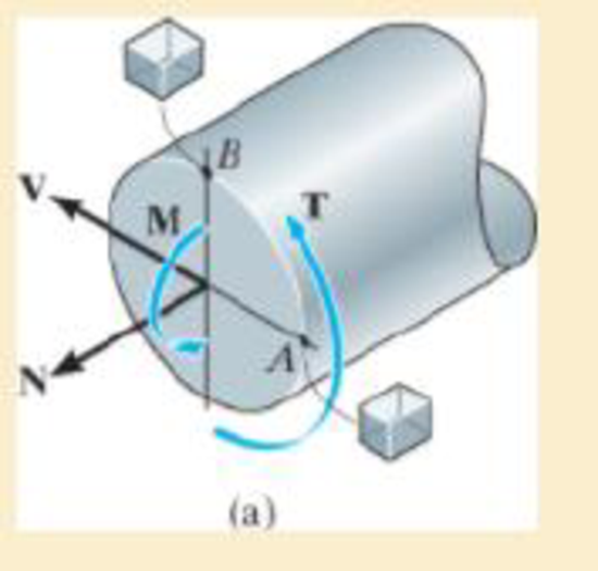
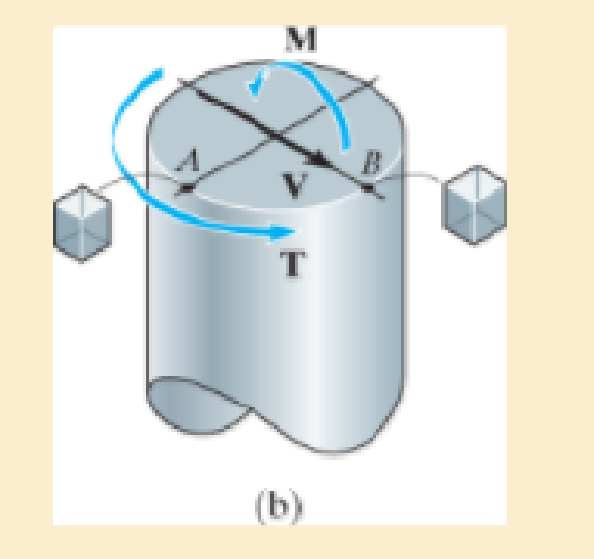
Chapter 8.2, Problem 8.2PP
Show the stress that each of these loads produce on differential elements located at point A and point B.
Expert Solution & Answer
Want to see the full answer?
Check out a sample textbook solution
Students have asked these similar questions
A rod has a solid circular cross section with a diameter of 40 mm is subjected to the shown loads. Determine the state of stress at point A.
OX=
Ixy =
Given:
The area moment of inertia of a solid circular cross section about its neutral axis is INA = (TR4)/4.
The polar moment of inertia of a solid circular cross section about its neutral axis is JNA = (TR4)/2.
The centroid of a semi-circle is located at 4R/(3n) from the horizontal axis representing the diameter line.
1500 N
-37 Mpa
64 Mpa
3.5 Mpa 7.3 Mpa
600 N
37 Mpa
-7.3 Mpa
300 mm
100 N·m
800 N
100 mm
B
The internal loadings act on the section. Show the stresses with their directions
that each of these loads produce on elements located at points from A to D.
NB
M.
Internal loadings
N
M
V
Element at point A
Element at point B
Element at point C
Element at point D
No Normal stress acts on the neutral axis. Is it true or false? How?
Chapter 8 Solutions
Mechanics of Materials (10th Edition)
Ch. 8.1 - If it is subjected to an internal pressure of p =...Ch. 8.1 - If it is subjected to an internal pressure of p =...Ch. 8.1 - The thin-walled cylinder can be supported in one...Ch. 8.1 - If the inner diameter of the tank is 22 in., and...Ch. 8.1 - Air pressure in the cylinder is increased by...Ch. 8.1 - Determine the maximum force P that can be exerted...Ch. 8.1 - A boiler is constructed of 8-mm-thick steel plates...Ch. 8.1 - 88. The steel water pipe has an inner diameter of...Ch. 8.1 - The steel water pipe has an inner diameter of 12...Ch. 8.1 - The A-36-steel band is 2 in. wide and is secured...
Ch. 8.1 - The gas pipe line is supported every 20 ft by...Ch. 8.1 - A pressure-vessel head is fabricated by welding...Ch. 8.1 - An A-36-steel hoop has an inner diameter of 23.99...Ch. 8.1 - The ring, having the dimensions shown, is placed...Ch. 8.1 - The inner ring A has an inner radius r1 and outer...Ch. 8.1 - Two hemispheres having an inner radius of 2 ft and...Ch. 8.1 - In order to increase the strength of the pressure...Ch. 8.2 - Show the results on the left segment.Ch. 8.2 - Show the stress that each of these loads produce...Ch. 8.2 - Fundamental Problems F81. Determine the normal...Ch. 8.2 - Show the results in a differential element at the...Ch. 8.2 - Determine the state of stress at point A on the...Ch. 8.2 - Determine the magnitude of the load P that will...Ch. 8.2 - Determine the state of stress at point B. Show the...Ch. 8.2 - Determine the state of stress at point A on the...Ch. 8.2 - Determine the state of stress at point A on the...Ch. 8.2 - Show the results in a differential element at the...Ch. 8.2 - Determine the shortest distance d to the edge of...Ch. 8.2 - The plate has a thickness of 20 mm and P acts...Ch. 8.2 - Plot the distribution of normal stress acting...Ch. 8.2 - Also, plot the normal-stress distribution over the...Ch. 8.2 - If the allowable normal stress for the steel is...Ch. 8.2 - If the applied force P = 1.50 kip, determine the...Ch. 8.2 - Determine the maximum normal stress on the cross...Ch. 8.2 - If the wood has an allowable normal stress of...Ch. 8.2 - Determine the maximum normal stress along section...Ch. 8.2 - Sketch the stress distribution along section aa of...Ch. 8.2 - Sketch the normal-stress distribution acting over...Ch. 8.2 - Determine the state of stress at points A and B,...Ch. 8.2 - If the force of 100 N is applied to the handles,...Ch. 8.2 - Determine the stress components at point A on the...Ch. 8.2 - Determine the stress components at point B on the...Ch. 8.2 - Determine the normal stress developed at points A...Ch. 8.2 - Sketch the normal-stress distribution acting over...Ch. 8.2 - Determine the state of stress at points A and B,...Ch. 8.2 - Determine the state of stress at point A on the...Ch. 8.2 - Determine the state of stress at point B on the...Ch. 8.2 - Determine the state of stress acting at point D....Ch. 8.2 - Determine the state of stress acting at point E....Ch. 8.2 - If it is subjected to the force system shown,...Ch. 8.2 - Solve Prob.840 for point B.Ch. 8.2 - Determine the stress components acting on the...Ch. 8.2 - Determine the stress components acting on the...Ch. 8.2 - Neglect the weight of the block.Ch. 8.2 - Neglect the weight of the block.Ch. 8.2 - He is supported uniformly by two bars, each having...Ch. 8.2 - Determine the state of stress at point A, and show...Ch. 8.2 - Determine the state of stress at point B, and show...Ch. 8.2 - Determine the state of stress at point C, and show...Ch. 8.2 - Determine the maximum radius e at which the load P...Ch. 8.2 - Specify the region to which this load can be...Ch. 8.2 - Determine the smallest force P that can be applied...Ch. 8.2 - The coiled spring is subjected to a force P. If we...Ch. 8.2 - The pins at C and D are at the same location as...Ch. 8.2 - Determine the state of stress at point A, and show...Ch. 8.2 - Determine the state of stress at point B, and show...Ch. 8.2 - Determine the stress components at points A and B...Ch. 8.2 - Determine the stress components at points C and D...Ch. 8.2 - Determine the stress components in the support...Ch. 8.2 - Determine the stress components in the support...Ch. 8.2 - If the force at the ram on the clamp at D is P= 8...Ch. 8.2 - Determine the maximum ram force P that can be...Ch. 8.2 - and an outer radius of 3.00 in. If the face of the...Ch. 8.2 - for points E and F.Ch. 8.2 - Determine the stress components at points A and B...Ch. 8.2 - Solve Prob.8-65 for points C and D.Ch. 8.2 - Due to internal gearing, this causes the block to...Ch. 8.2 - Determine the state of stress at point A and show...Ch. 8.2 - Solve Prob.868 for point B.Ch. 8.2 - Determine the stress components at point A. Sketch...Ch. 8.2 - for the stress components at point B.Ch. 8.2 - Determine the state of stress at point A at...Ch. 8.2 - Determine the state of stress at point B at...Ch. 8 - If it supports a cable loading of 800 lb,...Ch. 8 - Determine the state of stress at point E on the...Ch. 8 - Determine the state of stress at point F on the...Ch. 8 - The suspender arm AE has a square cross-sectional...Ch. 8 - If the cross section of the femur at section aa...Ch. 8 - If it has a mass of 5 kg/m, determine the largest...Ch. 8 - and is used to support the vertical reactions of...Ch. 8 - and is used to support the vertical reactions of...
Additional Engineering Textbook Solutions
Find more solutions based on key concepts
Convert the following quantities from English to SI units: a. 98 Btu/(hr-ft-F) b. 0.24 Btu/(lbm-F) C. 0.04 Ibm/...
Heating Ventilating and Air Conditioning: Analysis and Design
What parts are included in the vehicle chassis?
Automotive Technology: Principles, Diagnosis, And Service (6th Edition) (halderman Automotive Series)
What is the importance of modeling in engineering? How are the mathematical models for engineering processes pr...
Heat and Mass Transfer: Fundamentals and Applications
Consider a subsonic compressible flow in cartesian coordinates where the velocity potential is given by (x,y)=V...
Fundamentals of Aerodynamics
Select a mechanical component from Part 3 of this book (roller bearings, springs, etc.), go to the Internet, an...
Shigley's Mechanical Engineering Design (McGraw-Hill Series in Mechanical Engineering)
What types of polymers are most commonly blow molded?
DeGarmo's Materials and Processes in Manufacturing
Knowledge Booster


Learn more about
Need a deep-dive on the concept behind this application? Look no further. Learn more about this topic, mechanical-engineering and related others by exploring similar questions and additional content below.Similar questions
- Problem 3: The rod below has a diamter of 2 in. Determine the state of stress at point A, and show the results on a differential element located at this point. 400 lb x B 500 lb Z A 800 lb 10 in. 15 in.arrow_forward3. The composite bar consists of a 20-mm diameter steel segment AB and 50-mm diameter brass end segments DA and CB. Find the stress on each segment due to the applied loads. E of steel is 200 GPa and E of brass is 101 GPa. 250mm 250mm 250mm 50mm 20mm 50mm 75KN 100KN brass steel brass D B C 75KN 100KNarrow_forward5/5 find the normal stress at left of point C A 100 C 40 kN 50 kN 40 mm 70 10 kN 20 mm 30 mm 100 mm 300 mm 300 mm 200mm B.arrow_forward
- A force of 120 lb is applied to the edge of the member shown in the figure below. Neglect the weight of the member and determine the state of stress at points B and C using the superposition. 120 lb 4.5 in. | 4.5 in. -2.5 in 2.5 in B-arrow_forwardThe rigid beam BC is supported by rods (1) and (2). The cross-sectional area of rod (1) is 10 mm2. The cross-sectional area of rod (2) is 19 mm2. For a uniformly distributed load of w = 3.5 kN/m, determine the length a so that the normal stress is the same in each rod. Assume L = 4.55 m.arrow_forwardThe uniform 300-lb bar AB carries a 500-lb vertical force at A. The bar is supported by a pin at B and the 0:5-in. diameter cable CD. Find the stress in the cable. 4 ft A 3 ft 3 ft B. 500 Ibarrow_forward
- Two loads P act as shown, one parallel to (x0) and another parallel to z0; each load P equals 2.5 kN. The crankshaft dimensions are b1 = 80 mm, b2 = 135 mm, and b3 = 55 mm. The diameter of the upper shaft is d = 26 mm. Determine the normal stress at point B, which is located on the surface of the upper shaft at the yo axis. Yo Хо b3 Lütfen birini seçin: a. 149.606 MPa b. 324.676 MPa c. 139.544 MPa d. None e. 190.884 MPaarrow_forward3. A composite bar consists of an aluminum section rigidly fastened between bronze section and steel section as shown. Axial load as applied at the position indicated. Determine the stress in each section. 20KN 40KN- 180KN 100KN 800 mm 2 1000mm 2 1200mm 2 Prepared By: DTMarrow_forwardThe bearings at A and D exert only y and z components of force on the shaft as shown in Fig 7. Determine the smallest diameter of the shaft using maximum shear stress hypothesis theory if the allowable stress is 100 MPa.arrow_forward
- Module 4 Stress Distribution Point loads of 2000, 4000, and 6000 Ibs act at points A, B and C respectively, as shown below. Determine the increase in vertical stress at a depth of 10 feet below point D. A 10 feet B 10 feet C feet Darrow_forwardThe tube has an inner diameter d; = 20 mm and an outer diameter d, = 22 mm. It is subjected to an internal pressure of 1 MPa and the loads shown below. Determine the stress at point A and draw it on a stress element. 200 mm 400 mm 150 N-m 600 N 1500 N 800 Narrow_forwardDetermine the maximum value of the force P (kN) that can be applied to member AD if the allowable stress is 200 MPa and the maximum upward displacement of point A is 3 mm. Use E=100 GPa The values of the cross-sectional area, and L1, L2, and L3 are given in table below for each student. P A L1 12 kN L2 9 kN L3 LI (m) (m) Student Cross-sectional area L2 L3 ID (mm?) (m) 1.45 1131731 200 3.8 1.2arrow_forward
arrow_back_ios
SEE MORE QUESTIONS
arrow_forward_ios
Recommended textbooks for you
 Elements Of ElectromagneticsMechanical EngineeringISBN:9780190698614Author:Sadiku, Matthew N. O.Publisher:Oxford University Press
 Mechanics of Materials (10th Edition)Mechanical EngineeringISBN:9780134319650Author:Russell C. HibbelerPublisher:PEARSON
 Thermodynamics: An Engineering ApproachMechanical EngineeringISBN:9781259822674Author:Yunus A. Cengel Dr., Michael A. BolesPublisher:McGraw-Hill Education
 Control Systems EngineeringMechanical EngineeringISBN:9781118170519Author:Norman S. NisePublisher:WILEY
 Mechanics of Materials (MindTap Course List)Mechanical EngineeringISBN:9781337093347Author:Barry J. Goodno, James M. GerePublisher:Cengage Learning
 Engineering Mechanics: StaticsMechanical EngineeringISBN:9781118807330Author:James L. Meriam, L. G. Kraige, J. N. BoltonPublisher:WILEY
Elements Of Electromagnetics
Mechanical Engineering
ISBN:9780190698614
Author:Sadiku, Matthew N. O.
Publisher:Oxford University Press
Mechanics of Materials (10th Edition)
Mechanical Engineering
ISBN:9780134319650
Author:Russell C. Hibbeler
Publisher:PEARSON
Thermodynamics: An Engineering Approach
Mechanical Engineering
ISBN:9781259822674
Author:Yunus A. Cengel Dr., Michael A. Boles
Publisher:McGraw-Hill Education
Control Systems Engineering
Mechanical Engineering
ISBN:9781118170519
Author:Norman S. Nise
Publisher:WILEY
Mechanics of Materials (MindTap Course List)
Mechanical Engineering
ISBN:9781337093347
Author:Barry J. Goodno, James M. Gere
Publisher:Cengage Learning
Engineering Mechanics: Statics
Mechanical Engineering
ISBN:9781118807330
Author:James L. Meriam, L. G. Kraige, J. N. Bolton
Publisher:WILEY
EVERYTHING on Axial Loading Normal Stress in 10 MINUTES - Mechanics of Materials; Author: Less Boring Lectures;https://www.youtube.com/watch?v=jQ-fNqZWrNg;License: Standard YouTube License, CC-BY