Microelectronics: Circuit Analysis and Design
4th Edition
ISBN: 9780073380643
Author: Donald A. Neamen
Publisher: McGraw-Hill Companies, The
bartleby

Concept explainers

bartleby

Videos

Textbook Question
Book Icon
Chapter 9, Problem D9.18P

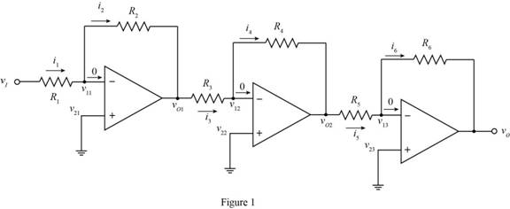
Design an amplifier system with three inverting op-amps circuits in cascadesuch that the overall closed-loop voltage gain is A v = v O / v I = 300 . Themaximum resistance is limited to 200 k Ω and the minimum resistance islimited to 20 k Ω . In addition, the maximum current in any resistor is to belimited to 60 μ A when v O = 6 V .

Expert Solution & Answer
Check Mark
To determine

The design parameters for an inverting op-amp circuit.

Answer to Problem D9.18P

The value of the resistance R2 is 100kΩ , R3 is 20kΩ , R4 is 120kΩ , R5 is 20kΩ and the value of the resistance R6 is 100kΩ .

Explanation of Solution

Calculation:

The required diagram for the inverting op amp with feedback is shown below.

The required diagram is shown in Figure 1.

  Microelectronics: Circuit Analysis and Design, Chapter 9, Problem D9.18P

The expression for the value of the voltage v11 is given by,

  v11=v21

Substitute 0 for v21 in the above equation.

  v11=0

The expression for the voltage v22 is given by,

  v22=v12

Substitute 0 for v22 in the above equation.

  v12=0

The expression for the value of the voltage v13 is given by.

  v13=v23

Substitute 0 for v23 in the above equation.

  v13=0

The expression for the output voltage of the first op-amp is given by,

  vO1=vI(R2R1)

The expression for the second voltage of the first op amp is given by,

  vO2=vO1(R2R4)

Substitute vI(R2R1) for vO1 in the above equation.

  vO2=vI(R2R1)(R4R3)

The expression for the voltage gain is given by,

  Av=vOvI

Substitute 300 for Av and 6V for vO in the above equation.

  300=6VvIvI=0.02V

Apply KCL at the negative terminal of the right most op-amp.

  v O20R5=0vOR6vO=v O2R6R5vOv O2=R6R5

Substitute vI(R2R1)(R4R3) for vO2 in the above equation.

  vOvI( R 2 R 1 )( R 4 R 3 )=R6R5vOvI=R6R5( R 2 R 1 )( R 4 R 3 )

Substitute Av for vOvI in the above equation.

  Av=R6R5(R2R1)(R4R3)

Substitute 300 for Av in the above equation.

  300=R6R5(R2R1)(R4R3)

The expression for the value of the current R6,min is given by,

  R6,min=vOi6,max

Substitute 60μA for i6,max and 6V for vO in the above equation.

  R6,min=6V60μA=0.1MΩ

The expression for the value off the voltage i5,max is given by,

  i5,max=i6,max

Substitute 60μA for i6,max in the above equation.

  i5,max=60μA

The expression for the value of the current i5,max is given by,

  i5,max=vOR 5,maxR 6,minR5,min

Substitute 60μA for i5,max , 0.1MΩ for R6,min and 6V for vO in the above equation.

  60μA=(6V)R 5,max0.1MΩR5,min

The expression to determine the range of the current is given by,

  |i2|=10|vO1R2|

Substitute 0.02V for vO1 and 0.2MΩ for R2 in the above equation.

  |i2|=10|0.02V0.2MΩ||i2|=1μA<60μA

The expression for the value of the mid stage gain is given by,

  vOvO1=6

Substitute (10)(0.02V) for vO2 in the above equation.

  v O2( 6)( 10)( 0.02V)=6vO=1.2V

The expression for the minimum value of the resistance R3,min is given by,

  R3,min=vO260μA

Substitute (10)(0.02V) for vO2 in the above equation.

  R3,min=( 10)( 0.02V)60μA=3.33kΩ

The maximum value of the resistance R3 to be used is 20kΩ .

The expression for the value of the resistance R4 is given by,

  R4=6R3

Substitute 20kΩ for R3 in the above equation.

  R4=6(20kΩ)120kΩ

The expression for the gain of the voltage gain of right most amplifier is given by,

  vOvO2=5

Substitute (10)(6)(0.02V) for vO2 in the above equation.

  vO=5(10)(6)(0.02V)=6V

The value for the current |i5|max is given by,

  |i5|max=60μA

The expression for the value of the resistance R5,min is given by,

  R5,min=| v O2| i 5 ||max

Substitute 60μA for |i5|max and (10)(6)(0.02V) for vO2 in the above equation.

  R5,min=|( 10)( 6)( 0.02V)| 60μA||=20kΩ

The expression for the maximum value of the resistance R6 is given by,

  R6=5R5

Substitute 20kΩ for R5 in the above equation.

  R6=5(20kΩ)=100kΩ

Conclusion:

Therefore, the value of the resistance R2 is 100kΩ , R3 is 20kΩ , R4 is 120kΩ , R5 is 20kΩ and the value of the resistance R6 is . 100kΩ .

Want to see more full solutions like this?

Subscribe now to access step-by-step solutions to millions of textbook problems written by subject matter experts!

Chapter 9 Solutions

Microelectronics: Circuit Analysis and Design

Ch. 9 - The noninverting op-amp in Figure 9.15 has a...Ch. 9 - Use superposition to determine the output voltage...Ch. 9 - Consider the voltage-to-current converter shown in...Ch. 9 - Consider the difference amplifier in Figure...Ch. 9 - In the difference amplifier shown in Figure...Ch. 9 - For the instrumentation amplifier in Figure 9.26,...Ch. 9 - An integrator with input and output voltages that...Ch. 9 - A current source has an output impedance of...Ch. 9 - Design the voltage-to-current converter shown in...Ch. 9 - All parameters associated with the instrumentation...Ch. 9 - Design the instrumentation amplifier in Figure...Ch. 9 - An integrator is driven by the series of pulses...Ch. 9 - Consider the summing op-amp in Figure 9.40. Let...Ch. 9 - Consider the bridge circuit in Figure 9.46. The...Ch. 9 - The resistance R in the bridge circuit in Figure...Ch. 9 - Describe the ideal op-amp model and describe the...Ch. 9 - Prob. 2RQCh. 9 - Describe the operation and characteristics of the...Ch. 9 - What is the concept of virtual ground?Ch. 9 - What is the significance of a zero output...Ch. 9 - When a finite op-amp gain is taken into account,...Ch. 9 - Prob. 7RQCh. 9 - Describe the operation and characteristics of the...Ch. 9 - Describe the voltage follower. What are the...Ch. 9 - What is the input resistance of an ideal...Ch. 9 - Prob. 11RQCh. 9 - Describe the operation and characteristics of an...Ch. 9 - Describe the operation and characteristics of an...Ch. 9 - Describe the operation and characteristics of an...Ch. 9 - Assume an op-amp is ideal, except for having a...Ch. 9 - The op-amp in the circuit shown in Figure P9.2 is...Ch. 9 - An op-amp is in an open-loop configuration as...Ch. 9 - Consider the equivalent circuit of the op-amp...Ch. 9 - Consider the ideal inverting op-amp circuit shown...Ch. 9 - Assume the op-amps in Figure P9.6 are ideal. Find...Ch. 9 - Consider an ideal inverting op-amp with R2=100k...Ch. 9 - (a) Design an inverting op-amp circuit with a...Ch. 9 - Consider an ideal op-amp used in an inverting...Ch. 9 - Consider the inverting amplifier shown in Figure...Ch. 9 - (a) Design an inverting op-amp circuit with a...Ch. 9 - (a) Design an inverting op-amp circuit such that...Ch. 9 - (a) In an inverting op-amp circuit, the nominal...Ch. 9 - (a) The input to the circuit shown in Figure P9.14...Ch. 9 - Design an inverting amplifier to provide a nominal...Ch. 9 - The parameters of the two inverting op-amp...Ch. 9 - Design the cascade inverting op-amp circuit in...Ch. 9 - Design an amplifier system with three inverting...Ch. 9 - Consider the circuit shown in Figure P9.19. (a)...Ch. 9 - The inverting op-amp shown in Figure 9.9 has...Ch. 9 - (a)An op-amp with an open-loop gain of Aod=7103 is...Ch. 9 - (a) For the ideal inverting op-amp circuit with...Ch. 9 - An ideal inverting op-amp circuit is to be...Ch. 9 - For the op-amp circuit shown in Figure P9.25,...Ch. 9 - The inverting op-amp circuit in Figure 9.9 has...Ch. 9 - (a) Consider the op-amp circuit in Figure P9.27....Ch. 9 - The circuit in Figure P9.28 is similar to the...Ch. 9 - Consider the ideal inverting summing amplifier in...Ch. 9 - (a) Design an ideal inverting summing amplifier to...Ch. 9 - Design an ideal inverting summing amplifier to...Ch. 9 - Consider the summing amplifier in Figure 9.14 with...Ch. 9 - The parameters for the summing amplifier in Figure...Ch. 9 - (a) Design an ideal summing op-amp circuit to...Ch. 9 - An ideal three-input inverting summing amplifier...Ch. 9 - A summing amplifier can be used as a...Ch. 9 - Consider the circuit in Figure P9.38. (a) Derive...Ch. 9 - Consider the summing amplifier in Figure 9.14(a)....Ch. 9 - Consider the ideal noninverting op-amp circuit in...Ch. 9 - (a) Design an ideal noninverting op-amp circuit...Ch. 9 - Consider the noninverting amplifier in Figure...Ch. 9 - For the circuit in Figure P9.43, the input voltage...Ch. 9 - Determine vO as a function of vI1 and vI2 for the...Ch. 9 - Consider the ideal noninverting op-amp circuit in...Ch. 9 - (a) Derive the expression for the closed-loop...Ch. 9 - The circuit shown in Figure P9.47 can be used as a...Ch. 9 - (a) Determine the closed-loop voltage gain...Ch. 9 - For the amplifier in Figure P9.49, determine (a)...Ch. 9 - Consider the voltage-follower circuit in Figure...Ch. 9 - (a) Consider the ideal op-amp circuit shown in...Ch. 9 - (a) Assume the op-amp in the circuit in Figure...Ch. 9 - Prob. 9.53PCh. 9 - A current-to-voltage converter is shown in Figure...Ch. 9 - Figure P9.55 shows a phototransistor that converts...Ch. 9 - The circuit in Figure P9.56 is an analog voltmeter...Ch. 9 - Consider the voltage-to-current converter in...Ch. 9 - The circuit in Figure P9.58 is used to drive an...Ch. 9 - Figure P9.59 is used to calculate the resistance...Ch. 9 - Consider the op-amp difference amplifier in Figure...Ch. 9 - Consider the differential amplifier shown in...Ch. 9 - Consider the differential amplifier shown in...Ch. 9 - Let R=10k in the differential amplifier in Figure...Ch. 9 - Consider the circuit shown in Figure P9.64. (a)...Ch. 9 - The circuit in Figure P9.65 is a representation of...Ch. 9 - Consider the adjustable gain difference amplifier...Ch. 9 - Assume the instrumentation amplifier in Figure...Ch. 9 - Consider the circuit in Figure P9.68. Assume ideal...Ch. 9 - Consider the circuit in Figure P969. Assume ideal...Ch. 9 - The instrumentation amplifier in Figure 9.26 has...Ch. 9 - Design the instrumentation amplifier in Figure...Ch. 9 - All parameters associated with the instrumentation...Ch. 9 - The parameters in the integrator circuit shown in...Ch. 9 - Consider the ideal op-amp integrator. Assume the...Ch. 9 - The circuit in Figure P9.75 is a first-order...Ch. 9 - (a) Using the results of Problem 9.75, design the...Ch. 9 - The circuit shown in Figure P9.77 is a first-order...Ch. 9 - (a) Using the results of Problem 9.77, design the...Ch. 9 - Prob. 9.79PCh. 9 - Consider the circuit in Figure 9.35. The diode...Ch. 9 - In the circuit in Figure P9.81, assume that Q1 and...Ch. 9 - Consider the circuit in Figure 9.36. The diode...Ch. 9 - Design an op-amp summer to produce the output...Ch. 9 - Design an op-amp summer to produce an output...Ch. 9 - Design a voltage reference source as shown in...Ch. 9 - Consider the voltage reference circuit in Figure...Ch. 9 - Consider the bridge circuit in Figure P9.87. The...Ch. 9 - Consider the bridge circuit in Figure 9.46. The...
Knowledge Booster
Background pattern image
Electrical Engineering
Learn more about
Need a deep-dive on the concept behind this application? Look no further. Learn more about this topic, electrical-engineering and related others by exploring similar questions and additional content below.
Recommended textbooks for you
Text book image
Introductory Circuit Analysis (13th Edition)
Electrical Engineering
ISBN:9780133923605
Author:Robert L. Boylestad
Publisher:PEARSON
Text book image
Delmar's Standard Textbook Of Electricity
Electrical Engineering
ISBN:9781337900348
Author:Stephen L. Herman
Publisher:Cengage Learning
Text book image
Programmable Logic Controllers
Electrical Engineering
ISBN:9780073373843
Author:Frank D. Petruzella
Publisher:McGraw-Hill Education
Text book image
Fundamentals of Electric Circuits
Electrical Engineering
ISBN:9780078028229
Author:Charles K Alexander, Matthew Sadiku
Publisher:McGraw-Hill Education
Text book image
Electric Circuits. (11th Edition)
Electrical Engineering
ISBN:9780134746968
Author:James W. Nilsson, Susan Riedel
Publisher:PEARSON
Text book image
Engineering Electromagnetics
Electrical Engineering
ISBN:9780078028151
Author:Hayt, William H. (william Hart), Jr, BUCK, John A.
Publisher:Mcgraw-hill Education,
Electrical Engineering: Ch 5: Operational Amp (2 of 28) Inverting Amplifier-Basic Operation; Author: Michel van Biezen;https://www.youtube.com/watch?v=x2xxOKOTwM4;License: Standard YouTube License, CC-BY