
Concept explainers
Videos
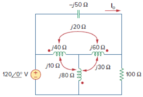
Find current Io in the circuit of Fig. 13.91.
Calculate the current
Answer to Problem 22P
The current
Explanation of Solution
Given data:
Refer to Figure 13.91 in the textbook for the coupled coil circuit.
Calculation:
In Figure 13.91, replace the coupled inductor by dependent source model by using Figure 13.8. The modified circuit as shown in Figure 1.
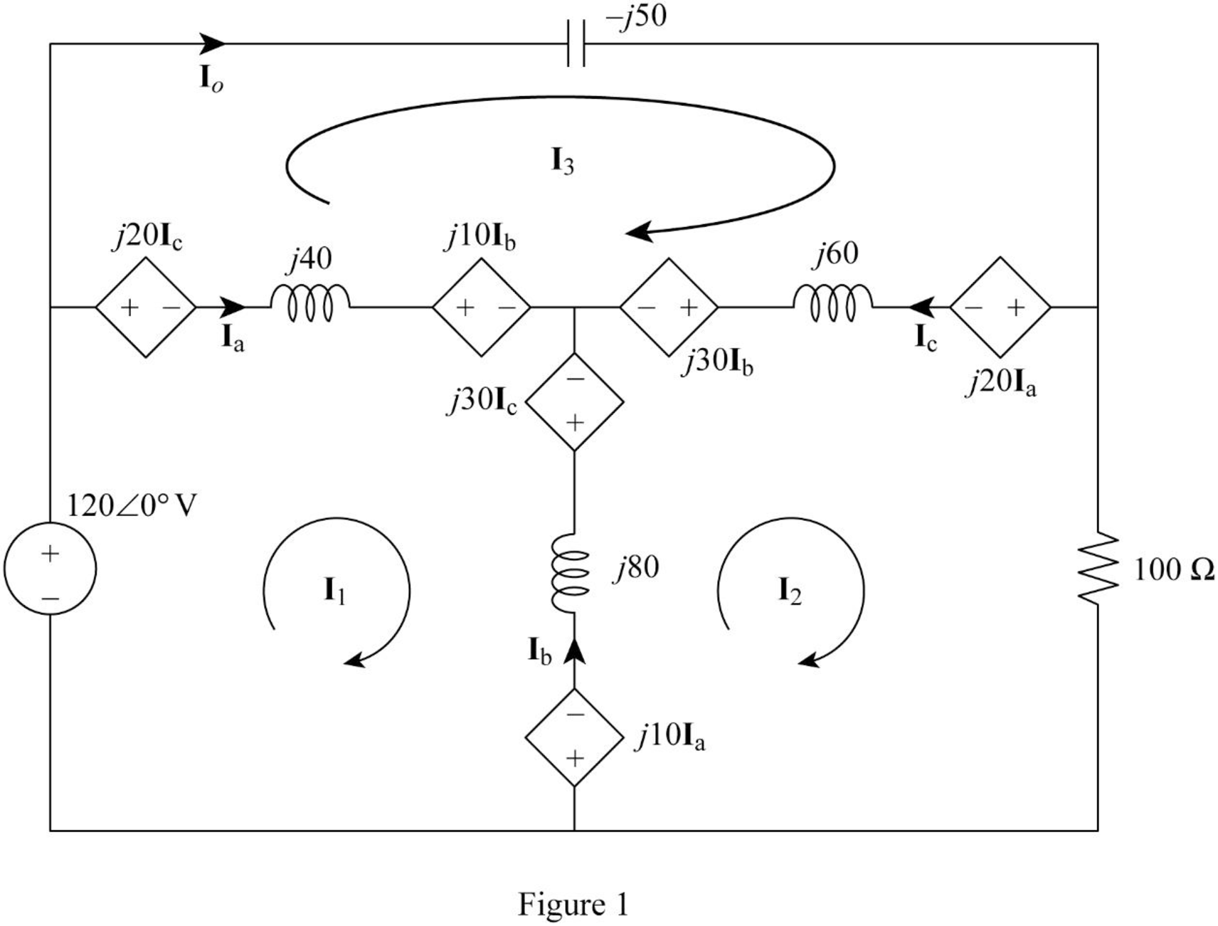
In Figure 1, consider the followings.
From Figure 1, consider that the loops 1, 2 and 3 contain the currents
Apply Kirchhoff's voltage law to the loop 1 in Figure 1.
Apply Kirchhoff's voltage law to the loop 2 in Figure 1.
Apply Kirchhoff's voltage law to the loop 3 in Figure 1.
Write equations (1), (2), and (3) in matrix form as follows.
Write the MATLAB code to solve the equation (4).
A = [j*100 j*(-60) j*(-40); j*(-60) (100+j*80) j*(-20); j*(-40) j*(-20) j*10];
B = [120; 0; 0];
C = inv(A)*B
The output in command window:
C =
0.45231 + 0.34154i
-0.19385 + 0.71077i
1.42154 + 2.78769i
From the MATLAB output, the currents
And
Write the expression for the current
Substitute
Conclusion:
Thus, the current
Want to see more full solutions like this?
Chapter 13 Solutions
Fundamentals of Electric Circuits


- 4,4 I (us) -40° FIG. 13.90arrow_forwardA coil has resistance of 5 ohm and capacitive reactance of 6 ohm . a) what is the impedance of the coil? b) what is the admittance of the coil?arrow_forwardThe impedance coil absorbs 250 watts when connected across 220 V, 60 Hz mains, it is then connected across 110 V, 25 Hz mains and also absorbs 250 watts. What is the inductance of the coil? Show complete solution.arrow_forward
- Electric Circuit Analysis 2020/2021 Doaa Hakim H.W. Find the current I in the following network: v = 10/20° V ZR = 20 Z = j2N Z = 40arrow_forwardDetermine the phasor currents I, and I₂ in the circuit of Fig. 13.13. 5Ω j2 Ω 100 /60° V 4₁ j6 Ω I + -j4Ω j3 Ωarrow_forwardAnalyze the following AC networks, define and calculate all voltages, resistances (if necessary) and ampers! 120 j6 2 50/0arrow_forward
- 13.18 Find the Thevenin equivalent to the left of the load H Z in the circuit of Fig. 13.87. ML k = 0.5 j2 Q all -j4 2 j5 N j20 Q 120 0° V Z 4 + j6 Qarrow_forwardWhat is the impedance of a transformer coil that has 340' of #18 copper wire and an inductance of 70mH at 60Hz? 1000’ of #18 copper wire is 16 ohms.arrow_forwardPlease answer 13.67arrow_forward
 Introductory Circuit Analysis (13th Edition)Electrical EngineeringISBN:9780133923605Author:Robert L. BoylestadPublisher:PEARSON
 Delmar's Standard Textbook Of ElectricityElectrical EngineeringISBN:9781337900348Author:Stephen L. HermanPublisher:Cengage Learning
 Programmable Logic ControllersElectrical EngineeringISBN:9780073373843Author:Frank D. PetruzellaPublisher:McGraw-Hill Education
 Fundamentals of Electric CircuitsElectrical EngineeringISBN:9780078028229Author:Charles K Alexander, Matthew SadikuPublisher:McGraw-Hill Education
 Electric Circuits. (11th Edition)Electrical EngineeringISBN:9780134746968Author:James W. Nilsson, Susan RiedelPublisher:PEARSON
 Engineering ElectromagneticsElectrical EngineeringISBN:9780078028151Author:Hayt, William H. (william Hart), Jr, BUCK, John A.Publisher:Mcgraw-hill Education,