
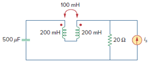
In the circuit of Fig. 13.93,
- (a) find the coupling coefficient,
- (b) calculate vo,
- (c) determine the energy stored in the coupled inductors at t = 2 s.
(a)
Calculate the coupling coefficient of the circuit in Figure 13.93.
Answer to Problem 24P
The coupling coefficient is
Explanation of Solution
Given data:
Refer to Figure 13.93 in the textbook for the circuit with coupled coils.
The value of
Calculation:
Consider the expression for the coefficient of coupling in the coupled coils.
Substitute 1 H for M, 4 H for
Conclusion:
Thus, the coupling coefficient is
(b)
Calculate the voltage
Answer to Problem 24P
The value of voltage
Explanation of Solution
Given data:
From Figure 13.93, the value of
Calculation:
Write the expression for the inductive reactance.
Write the expression for the capacitive reactance.
Substitute 4 H for
Substitute 2 H for
Substitute 1 H for
Substitute
Calculate load impedance
Modify the Figure 13.93 by transforming the time-domain circuit with coupled-coils to frequency domain of the circuit with coupled-coils. The frequency domain equivalent circuit is shown in Figure 1.
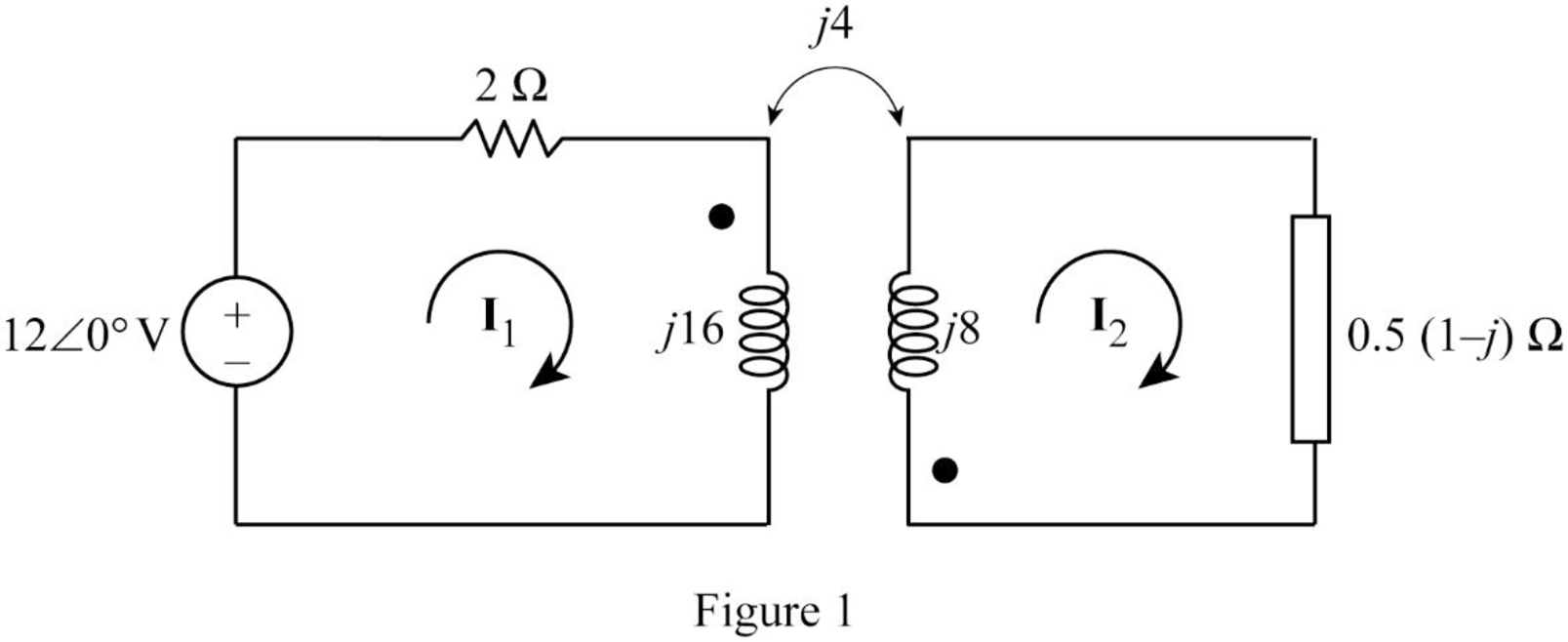
From Figure 1, consider that the loops 1 and 2 contain the currents
Apply Kirchhoff's voltage law to the loop 1 in Figure 1.
Apply Kirchhoff's voltage law to the loop 2 in Figure 1.
Write equations (3) and (4) in matrix form as follows.
Write the MATLAB code to solve the equation (5).
A = [(1+j*8) j*2;j*4 (0.5+j*7.5)];
B = [6; 0];
I = inv(A)*B
The output in command window:
I =
0.13036 - 0.84468i
-0.09912 + 0.44389i
From the MATLAB output, the currents
And
Write the expression for the voltage
Substitute
Convert the phasor form to time domain form.
Conclusion:
Thus, the value of voltage
(c)
Calculate the stored energy in the coupled coils at
Answer to Problem 24P
The energy stored in the coupled coils is
Explanation of Solution
Calculation:
From part (b), write the currents
Substitute 2 s for t in Equation (6).
Substitute 2 s for t in Equation (7).
Write the expression for the total energy stored in the coupled coils.
Substitute 4 H for
Conclusion:
Thus, the energy stored in the coupled coils is
Want to see more full solutions like this?
Chapter 13 Solutions
Fundamentals of Electric Circuits
Additional Engineering Textbook Solutions
Microelectronics: Circuit Analysis and Design
ANALYSIS+DESIGN OF LINEAR CIRCUITS(LL)
Programmable Logic Controllers
Electric Circuits (10th Edition)
Electric machinery fundamentals
Electric Motors and Control Systems

- A coil having a 240V source has a current of 10.5 A when the frequency is set to 60 Hz. When the frequency is changed to 16 Hz, the resulting current is now 15.5 A. Find the inductance, L, of the coil (in mH). (use 2 decimal places. No unit required)arrow_forwarda) Calculate the source voltage U. b) Calculate the capacitance C of the capacitor. c) Calculate the active power d) Determine the impedance of the circuitarrow_forward1- In a buck DC/DC converter: ton V₁ = 100 V, R= 80, D ==0.8, f == 20000 Hz, L = 200 μH, Find: a) average voltage and current of the load Vala. b) maximum and minimum current of inductor. c) Voltage ripple of the capacitor. d) the average input current. e) draw the figure of the inductor current. C1 = 40 Micro farad Q Vd - İd K C1 ww + Voarrow_forward
- What is the inductance L of the primary of a transformer whose input is 150V at 60 Hz and the current drawn is 3.5 Amps? Assume no current in the secondary.arrow_forwardProcedure (A) Buck Converter (Duty Cycle) 1. Make connections of power supply, capacitor, inductor, MOSFET and load resistor to build the buck converter. Vs=100 V=18 r=0.5% R=10 ohm f=40 KH Calculate minimum inductance: Lmin=(1-D)( R)/2f Calculate minimum capacitance: Cmin=1-D/8L(AVo/No) f^2 Calculate duty ratio: D=Vo/Vinarrow_forwardA 3 ph F.W. 1/2 controlled converter with highly inductive load ,R=10, V=400 RMS and Out=15A.Find alpha.arrow_forward
- 3- The self-inductance of an iron-cored coil is a function of: a) The geometry of the coil only. b) The current passing through it only. c) The frequency of the applied voltage only. d) All of the above factors. 4- The most effootiuaarrow_forwardL.) Two identical coupled coils have an equivalent inductance of 100 mH when connected series aiding and 50 mH in series opposing. What are the values of the self-inductance L1 and L2? a. 3.75 mH b. 375 mH c. 0.375 mH d. 37.50 mHarrow_forwardA coil with an inductance of 100 mH is connected in series with a resistance of 20 Ω. Find the active, reactive, and apparent power of 110 V AC current with a frequency of 25 Hz, current, resistance, and voltage at the coil ends in this system.arrow_forward
- If a Marx generator is required to perform a 170 kV lightning impulse test, and you have capacitors rated at 60 kVdc available: (a) If the voltage efficiency is 90%, how many stages, n, should the Marx generator have, and what should the dc charging voltage, Vo, be? Using the output parameters to calculate the erected capacitance first, what should be the capacitance per stage if the minimum required stored energy for the test is 900 J? (b)arrow_forwardLesson: Resistance, Reactance and Impedance A 100 uF capacitor has a minimal internal resistance of 17.5 ohms. What will be its equivalent impedance at 25-Hz?arrow_forwardA 210-microfarad capacitor is connected in parallel with a coil of 25-ohm resistance and 220mH inductance having a supply voltage of 230V, 50Hz. Solve the following: a. Power Factor of the Circuit b. Total Current c. Active/Real Power d. Reactive Powerarrow_forward
 Introductory Circuit Analysis (13th Edition)Electrical EngineeringISBN:9780133923605Author:Robert L. BoylestadPublisher:PEARSON
 Delmar's Standard Textbook Of ElectricityElectrical EngineeringISBN:9781337900348Author:Stephen L. HermanPublisher:Cengage Learning
 Programmable Logic ControllersElectrical EngineeringISBN:9780073373843Author:Frank D. PetruzellaPublisher:McGraw-Hill Education
 Fundamentals of Electric CircuitsElectrical EngineeringISBN:9780078028229Author:Charles K Alexander, Matthew SadikuPublisher:McGraw-Hill Education
 Electric Circuits. (11th Edition)Electrical EngineeringISBN:9780134746968Author:James W. Nilsson, Susan RiedelPublisher:PEARSON
 Engineering ElectromagneticsElectrical EngineeringISBN:9780078028151Author:Hayt, William H. (william Hart), Jr, BUCK, John A.Publisher:Mcgraw-hill Education,