
Videos
The expression for force versus piston travel d up to d = 10 mm.
Answer to Problem 2.82P
The expression for Force F versus piston travel d is
And the value of force F at d =10 mm is 127996.71 N
Explanation of Solution
Given data:
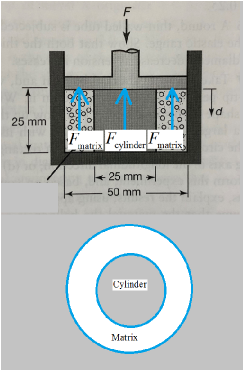
A cylindrical is surrounded by a compressible matrix. Cylindrical slug is compressed vertically by a force F which is to be determined. When the force F is acted then there will be the generation of stress inside the cylindrical slug and pressure is also generated inside the compressible matrix. The force acted will be equal to the force generated inside the cylindrical slug plus the force generated inside the matrix.
Calculation:
Drawing the free body diagram of the given system,
From the free body diagram, it can be written as,
Area of the matrix and cylinder can be given as −
Calculating the force exerted by the matrix:-
The strain developed inside the cylinder for deformation of height d is −
True strain inside the cylinder would be −
Writing true stress-true strain relation,
The force will be given as,
From equation (1), (2) and (3),
The above is the required expression for force versus d .
Putting d = 10 mm we get,
Hence, the expression for Force F versus piston travel d is
And the value of force F at d =10 mm is 127996.71 N
Want to see more full solutions like this?
Chapter 2 Solutions
EBK MANUFACTURING PROCESSES FOR ENGINEE


- (Solid Mechanics) This finite element model is composed of 4 linear bar elements, each with a cross section of 10 mm² and material properties (E = 6 GPa, v=0.3). A weight of 200 N is applied and the nodes are named as shown below. (1) Compute the reaction forces. (2) What are the reaction forces when the weight is tripled to be 600 N? Find the solution without repeating the FEA. Explain why you can get the quick answer.arrow_forwardA rubber block with dimensions of 120x120x120 mm is compressed in a rigid mold cavity with a vertical force of F = 120 kN.In the rubber block,a) The stress in the vertical (direction y)b) Stress in the horizontal direction (in the x direction)c) Find the value (mm) of the deformation in the vertical (y direction).Rubber block,Elasticity modulus E = 820 MPaPoisson ratio v = 0.4arrow_forwardA component consists of two horizontal concentric solid cylinders, A and B, fixed together as shown in the diagram below. Cylinder A has a diameter of 40 mm, a length of 350 mm and is made of steel having a density of 7850 kg/m³. Cylinder B has a diameter of 50 mm, a length of 500 mm and is made of aluminium having a density of 2700 kg/m³. Go Cylinder A - Steel |Cylinder B -Aluminium 350 mm 500 mm Calculate: a) The volume of each cylinder. b) The mass of each cylinder. c) The weight of each cylinder. d) The horizontal distance i from the centre of gravity (G) of the component to its left hand end. IXarrow_forward
- 3. A board whose width changes as w(x) = 2(√I-√√) (0 ≤ x ≤ L), as shown is fixed on the left edge. Here L is the length of the board. The material has an area mass density (per unit area) of pkg/m² dA w(x) = 2(√L-√x) L F(x,y) a) What is the weight of the board? Derive it by integrating weight of a differential element, dA located at z and that has a width w(r) as shown. b) What is the moment of the weight of the board about the y-axis. Derive it by integrating the moment applied by the differential element, dA, located at distance r away from the fixed edge. c) An additional distributed load, that is constant along the width but changes with distance as F(x, y) = kx² N/m², is applied on the board (the gray surface in the figure is the force function). What is the moment applied by this external load on the fixed edge. Solve this using a similar approach as step (b).arrow_forwardProblem 1 Consider a plate formed by a non-homogeneous material with Young's modulus E(z) = Eo-zE, with Eo, E1 > 0 and Poisson's ratio v. The plate has total thickness h, the reference plane is located at the center of the plate, and N and Ny are applied at z = 0. Find the stiffness matrix of the plate.arrow_forwardElement 1 Ук ** Answer in MPa. 2 cm Element 2 Assume the reaction forces at the origin were solved to be Rf = [325, 100, 0] N and = Rm [10, -2, 5] Nm. We will consider a hypothetical cut at the connection of the dolly to the axle. Z is positive out of the page. What is the value of normal stress in the x-direction Ox for element 2? Answer options: a) Ox < -300 b) -300 ≤ Ox < -100 c) -100 ≤ Ox < -200 d) 0 ≤ Ox < 100 e) 100 ≤ Ox < 300 f) 300 ≤ Oxarrow_forward
- SECTION B- STRUCTURES-DR LARISA MALYSHEVA QB1 DIRECT STRESS Two round solid bars of different materials are connected (in parallel) and have a common tensile force, P, of 190 kN is applied,ras shown in Figure QB1. For each bar, determine the: a) b) Stress. Strain and Strain in the diameter. Use the following information. Clearly show all your derivations. The original length of each bar = 1.7m. %3D Steel Bar: 32mm Dia. Poisson's Ratio = 0.31 18mm Dia. Young's Modulus = 210 GPa %3D Steel Aluminium Bar Bar Common Connection Aluminium Bar: P = 190 kN Poisson's Ratio = 0.34 Young's Modulus = 68 GPa Fig QB1arrow_forwardThe composite plate is made from both steel (A) and brass (B) segments. Take pt = 7.85 Mg/m" and pr = 8.74 Mg/m. Suppose that L = 200 mm. (Figure 1) Part A Determine the mass Express your answer to three significant figures and include the appropriate units. Value kg m = Subrnit Request Answer Part B Determine location (2, y, 2) of Its mass center G. Express your answers using three significant figures separated by commas. vec Figure mm Submit Request Answer Provide Feedback Next > 150 mim 30 mmarrow_forwardThe aluminum rod BC (G= 26 GPa) is bonded to the brass rod AB (G= 39 GPa). Each rod is solid and has a diameter of 12 mm. Take T= 124 N-m. NOTE: This is a multi-part question. Once an answer is submitted, you will be unable to return to this part. 200 mm Brass B Aluminum 300 mm T Determine the angle of twist at B. The angle of twist at B is[arrow_forward
- The elongation of a bar of uniform cross section subjected to an axial force is given by the equation (omega)= PL/AE What are the dimensions of E if (omega) and L are lengths, P is a force, and A is an area?arrow_forwardP2. Design a cylindrical thin-wall composite fuselage for storing compressed natural gas at a maximum operating pressure of 20 MPa. The pressure vessel is made by filament winding with fibres at ±45 degrees and is required to sustain three times the operating pressure without failure. The radius of the cylindrical pressure vessel must be 0.25 meters, and the length must be 2 meters. The maximum strengths of the composite ply are equal to 2000 MPa in the fibre direction and zero perpendicular to the fibre direction. Determine the minimum number of composite plies required to meet the design requirements. Hoop stress and longitudinal stress of cylinder are Answers: 38 plies (when tp=1 mm) t pr 21arrow_forwardm = 18kg and L = 1.28 marrow_forward
 Elements Of ElectromagneticsMechanical EngineeringISBN:9780190698614Author:Sadiku, Matthew N. O.Publisher:Oxford University Press
 Mechanics of Materials (10th Edition)Mechanical EngineeringISBN:9780134319650Author:Russell C. HibbelerPublisher:PEARSON
 Thermodynamics: An Engineering ApproachMechanical EngineeringISBN:9781259822674Author:Yunus A. Cengel Dr., Michael A. BolesPublisher:McGraw-Hill Education
 Control Systems EngineeringMechanical EngineeringISBN:9781118170519Author:Norman S. NisePublisher:WILEY
 Mechanics of Materials (MindTap Course List)Mechanical EngineeringISBN:9781337093347Author:Barry J. Goodno, James M. GerePublisher:Cengage Learning
 Engineering Mechanics: StaticsMechanical EngineeringISBN:9781118807330Author:James L. Meriam, L. G. Kraige, J. N. BoltonPublisher:WILEY