
Concept explainers
Calculate the value of
Answer to Problem 91P
The value of
Explanation of Solution
Given data:
Refer Figure 3.127 in the textbook for the transistor circuit.
The common-emitter current gain
The base-emitter voltage
Formula used:
Write the expression for collector current in transistor.
Here,
Write the expression for emitter current of transistor.
Calculation:
The Thevenin resistance of the input circuit is the parallel combination of
The Thevenin voltage of the input circuit is the voltage across
Modify the Figure 3.127 with the incorporation of Thevenin equivalent circuit as shown in Figure 1.
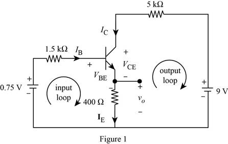
Apply Kirchhoff’s voltage law to input loop in Figure 1.
Substitute equation (2) in (3).
Substitute
Simplify the above equation as follows.
From Figure 1, write the expression for voltage
Substitute equation (2) in (4).
Substitute
Apply Kirchhoff’s voltage law to output loop in Figure 1.
Substitute equation (1) in (6).
Substitute
Conclusion:
Therefore, the value of
Want to see more full solutions like this?
Chapter 3 Solutions
Fundamentals of Electric Circuits


- - Find the Thévenin circuit for the network within the shaded area of Figure below:.. E. Q+10V R 1.4 kf CRL E, 6-6V Warrow_forwardQ3: Obtain the Thevenin equivalent circuits at terminals a-b for the circuit in figure shown below: R, V, I 2002 2% Vo- www 10 (2 3 A a obarrow_forwardPractice: 3.3 Find vo and io in the circuit of the following figure: 6A 22 Answer: 8 V, 4 A. Iniyersity of Thi-Qar/Department of Electrical and Electronic Engineering-Lectures are prepared by M.Sc. Ali Kareem lowander and Matthew N. 0. Sadiku. Page 4 wwarrow_forward
- use Superposition principle: a) determine the contribution from the voltage source alone. b) determine the contribution from the current source alone. c)determine the total current with both sources active.arrow_forward2. What are the advantages of Thevenin's theorem 3.Define the voltage source and current source . What are the difference between them.arrow_forwardQ5 Using superposition theorem find the output voltage Vo for the circuit below. All resistances in ohm. 4A www. 352 25 € GAT 6A 6varrow_forward
- Determine the VD for the circuits below:arrow_forwardMesh analysis employs the method of: Select one: O a. KCL O b. KVL O c. Neither KVL nor KCL Od. Both KVL and KCLarrow_forward1. Solve mathematically the vo for each network (a) and (b) as shown below. 2. Compare the computed vo using the results in Multisim. 4 V 2.2 k2 2.2 kQ Si 4 V 8 V (b) (a)arrow_forward
- Q3. Sketch Vo for the circuit shown below? R * 19arrow_forwardUse superposition to calculate the voltage Vo, if Is = 3, R = 2, and Vs = 12.arrow_forward1.Four 20-0 resistors are connected in parallel and the combination is connected to a 20-V emf device. The current in the device is =. Aarrow_forward
 Introductory Circuit Analysis (13th Edition)Electrical EngineeringISBN:9780133923605Author:Robert L. BoylestadPublisher:PEARSON
 Delmar's Standard Textbook Of ElectricityElectrical EngineeringISBN:9781337900348Author:Stephen L. HermanPublisher:Cengage Learning
 Programmable Logic ControllersElectrical EngineeringISBN:9780073373843Author:Frank D. PetruzellaPublisher:McGraw-Hill Education
 Fundamentals of Electric CircuitsElectrical EngineeringISBN:9780078028229Author:Charles K Alexander, Matthew SadikuPublisher:McGraw-Hill Education
 Electric Circuits. (11th Edition)Electrical EngineeringISBN:9780134746968Author:James W. Nilsson, Susan RiedelPublisher:PEARSON
 Engineering ElectromagneticsElectrical EngineeringISBN:9780078028151Author:Hayt, William H. (william Hart), Jr, BUCK, John A.Publisher:Mcgraw-hill Education,