
Mechanics of Materials (10th Edition)
10th Edition
ISBN: 9780134319650
Author: Russell C. Hibbeler
Publisher: PEARSON
expand_more
expand_more
format_list_bulleted
Concept explainers
Videos
Textbook Question
Chapter 3.4, Problem 3.12FP
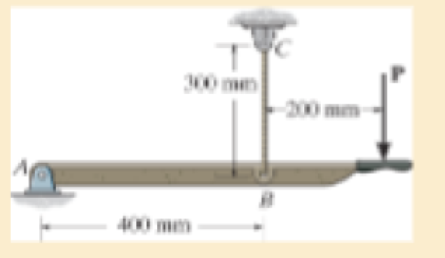
If the elongation of wire BC is 0.2 mm after the force P is applied, determine the magnitude of P. The wire is A-36 steel and has a diameter of 3 mm.
Expert Solution & Answer

Trending nowThis is a popular solution!

Students have asked these similar questions
4.
The rigid lever arm is supported by two A-36 steel
wires having the same diameter of 4 mm. If a force of
P = 3 kN is applied to the handle, determine the force
developed in both wires and their corresponding elongations.
Consider A-36 steel as an elastic-perfectly plastic material.
450 mm
150 mm
150 mm
30
300 mm
B.
The pole is supported by a pin at C and an A-36 steel guy wire AB. If the wire has a diameter of 0.2 in., determine how much it stretches when a horizontal force of 2.5 kip acts on the pole.
The rigid lever arm is supported by two A-36 steel wires having the same diameter of 4 mm. If a force of P = 3 kN is applied to the handle, determine the force developed in both wires and their corresponding elongations. Consider A-36 steel as an elastic perfectly plastic material.
Chapter 3 Solutions
Mechanics of Materials (10th Edition)
Ch. 3.4 - Define a homogeneous material.Ch. 3.4 - Indicate the points on the stress-strain diagram...Ch. 3.4 - Define the modulus of elasticity E.Ch. 3.4 - At room temperature, mild steel is a ductile...Ch. 3.4 - Engineering stress and strain are calculated using...Ch. 3.4 - As the temperature increases the modulus of...Ch. 3.4 - A 100-mm-long rod has a diameter of 15 mm. If an...Ch. 3.4 - A bar has a length of 8 in. and cross-sectional...Ch. 3.4 - A 10-mm-diameter rod has a modulus of elasticity...Ch. 3.4 - The material for the 50-mm-long specimen has the...
Ch. 3.4 - The material for the 50-mm-long specimen has the...Ch. 3.4 - If the elongation of wire BC is 0.2 mm after the...Ch. 3.4 - A tension test was performed on a steel specimen...Ch. 3.4 - Data taken from a stress-strain test for a ceramic...Ch. 3.4 - Data taken from a stress-strain test for a ceramic...Ch. 3.4 - The stress-strain diagram for a steel alloy having...Ch. 3.4 - The stress-strain diagram for a steel alloy having...Ch. 3.4 - The stress-strain diagram for a steel alloy having...Ch. 3.4 - The rigid beam is supported by a pin at C and an...Ch. 3.4 - The rigid beam is supported by a pin at C and an...Ch. 3.4 - Acetal plastic has a stress-strain diagram as...Ch. 3.4 - The stress-strain diagram for an aluminum alloy...Ch. 3.4 - The stress-strain diagram for an aluminum alloy...Ch. 3.4 - The stress-strain diagram for an aluminum alloy...Ch. 3.4 - A bar having a length of 5 in. and cross-sectional...Ch. 3.4 - The rigid pipe is supported by a pin at A and an...Ch. 3.4 - The rigid pipe is supported by a pin at A and an...Ch. 3.4 - Direct tension indicators are sometimes used...Ch. 3.4 - The rigid beam is supported by a pin at C and an...Ch. 3.4 - The rigid beam is supported by a pin at C and an...Ch. 3.4 - The stress-strain diagram for a bone is shown, and...Ch. 3.4 - The stress-strain diagram for a bone is shown and...Ch. 3.4 - The two bars are made of a material that has the...Ch. 3.4 - The two bars are made of a material that has the...Ch. 3.4 - The pole is supported by a pin at C and an A-36...Ch. 3.4 - The bar DA is rigid and is originally held in the...Ch. 3.7 - A 100-mm-long rod has a diameter of 15 mm. If an...Ch. 3.7 - A solid circular rod that is 600 mm long and 20 mm...Ch. 3.7 - A 20-mm-wide block is firmly bonded to rigid...Ch. 3.7 - A 20-mm-wide block is bonded to rigid plates at...Ch. 3.7 - The acrylic plastic rod is 200 mm long and 15 mm...Ch. 3.7 - The plug has a diameter of 30 mm and fits within a...Ch. 3.7 - The elastic portion of the stress-strain diagram...Ch. 3.7 - The elastic portion of the stress-strain diagram...Ch. 3.7 - The brake pads for a bicycle tire are made of...Ch. 3.7 - The lap joint is connected together using a 1.25...Ch. 3.7 - The lap joint is connected together using a 1.25...Ch. 3.7 - The rubber block is subjected to an elongation of...Ch. 3.7 - The shear stress-strain diagram for an alloy is...Ch. 3.7 - A shear spring is made from two blocks of rubber,...Ch. 3 - The elastic portion of the tension stress-strain...Ch. 3 - The elastic portion of the tension stress-strain...Ch. 3 - The rigid beam rests in the horizontal position on...Ch. 3 - The wires each have a diameter of 12 in., length...Ch. 3 - The wires each have a diameter of 12 in., length...Ch. 3 - diameter steel bolts. If the clamping force in...Ch. 3 - The stress-strain diagram for polyethylene, which...Ch. 3 - The pipe with two rigid caps attached to its ends...Ch. 3 - The 8-mm-diameter bolt is made of an aluminum...Ch. 3 - An acetal polymer block is fixed to the rigid...
Knowledge Booster


Learn more about
Need a deep-dive on the concept behind this application? Look no further. Learn more about this topic, mechanical-engineering and related others by exploring similar questions and additional content below.Similar questions
- 3. At temperature T₁, the two rigidly connected rods just fit the rigid supports. If both sections are identical except for the diameter, prove that the following equations are true when temperature rises to T₂. a. F= b. OAB C. OBC A x(T₂-T₁)лd²E 20 x(T₂-T₁)E 5 9x(T₂-T₁)E 5 -1/2- d B 1/12- d Carrow_forward3. If P = 150 kN, determine the decrease in the diameter of rod BC. Rod BC is made of A-36 steel of E = 200GPa and has a diameter of 40 mm. Use v = 0.42. P -1 m- -1 m P -1m- B 0.75 m 1 marrow_forwardA 20-mm-wide block is firmly bonded to rigid plates at its top and bottom. When the force P is applied the block deforms into the shape shown by the dashed line. Determine the magnitude of P. The block’s material has a modulus of rigidity of G = 26 GPa. Assume that the material does not yield and use small-angle analysis.arrow_forward
- F8-12. If the elongation of wire BC is 0.2 mm after the force Pis applied, determine the magnitude of P. The wire is A-36 steel and has a diameter of 3 mm. 300 mm -200 mm- E 400 mmarrow_forwardThe rigid bar AB and CD are supported by pins at A and D. the vertical rods are made of aluminum and bronze. Determine the vertical displacement of the point where the force P= 10 kips is applied. Neglect the weight of the members.arrow_forwardIf the force P equals 2500 lbs. Determine the maximum tensile stress in the section of the hook clamp where the 0.5 diameter dimension is shownarrow_forward
- If the allowable tensile stress for wires AB and AC is sallow = 180 MPa, and wire AB has a diameter of 5 mm and AC has a diameter of 6 mm, determine the greatest force P that can be applied to the chain.arrow_forward1-Determine the elongation of the steel bar 1m long and 1.5 cm cross-sectional area when subjected to a pull of 1500 kg. Take E=2*10 kg/cm ?arrow_forwardThe long bolt passes through the 70.4-mm-thick plate. If the force in the bolt shank is 9.5 KN, then the average shear stress (MPa) along the cylindrical area of the plate defined by the section lines a-a is: O a. 0.00 O b. 21.00 O c. 2.39 O d. 4.77 O e. 1.19 18 mm b b 8 mm Time left 0:45:52 a 7 mm YouTube The wood beam has an allowable shear stress of 15 MPa, the maximum shear force V (kN) that can be lind to the cross section is:arrow_forward
- The steel strip has a uniform thickness of 50 mm. Compute the elongation of the strip caused by the 500-kN axial force. The modulus of elasticity of steel is 200 GPa.arrow_forwardThe links of the chains are made of steel that has a working stress of 300 MPa in tension. If the chain is to support the force P = 45 kN, determine the smallest safe diameter d of the links in mm.arrow_forwardA steel bar 300 mm long, 50 mm wide and 40 mm thick is subjected to a pull of 300 kN in the direction of length. Determine the change in volume. Take E = 2x10⁵ N/mm2and μ= 0.25.arrow_forward
arrow_back_ios
SEE MORE QUESTIONS
arrow_forward_ios
Recommended textbooks for you
 Elements Of ElectromagneticsMechanical EngineeringISBN:9780190698614Author:Sadiku, Matthew N. O.Publisher:Oxford University Press
 Mechanics of Materials (10th Edition)Mechanical EngineeringISBN:9780134319650Author:Russell C. HibbelerPublisher:PEARSON
 Thermodynamics: An Engineering ApproachMechanical EngineeringISBN:9781259822674Author:Yunus A. Cengel Dr., Michael A. BolesPublisher:McGraw-Hill Education
 Control Systems EngineeringMechanical EngineeringISBN:9781118170519Author:Norman S. NisePublisher:WILEY
 Mechanics of Materials (MindTap Course List)Mechanical EngineeringISBN:9781337093347Author:Barry J. Goodno, James M. GerePublisher:Cengage Learning
 Engineering Mechanics: StaticsMechanical EngineeringISBN:9781118807330Author:James L. Meriam, L. G. Kraige, J. N. BoltonPublisher:WILEY
Elements Of Electromagnetics
Mechanical Engineering
ISBN:9780190698614
Author:Sadiku, Matthew N. O.
Publisher:Oxford University Press
Mechanics of Materials (10th Edition)
Mechanical Engineering
ISBN:9780134319650
Author:Russell C. Hibbeler
Publisher:PEARSON
Thermodynamics: An Engineering Approach
Mechanical Engineering
ISBN:9781259822674
Author:Yunus A. Cengel Dr., Michael A. Boles
Publisher:McGraw-Hill Education
Control Systems Engineering
Mechanical Engineering
ISBN:9781118170519
Author:Norman S. Nise
Publisher:WILEY
Mechanics of Materials (MindTap Course List)
Mechanical Engineering
ISBN:9781337093347
Author:Barry J. Goodno, James M. Gere
Publisher:Cengage Learning
Engineering Mechanics: Statics
Mechanical Engineering
ISBN:9781118807330
Author:James L. Meriam, L. G. Kraige, J. N. Bolton
Publisher:WILEY
EVERYTHING on Axial Loading Normal Stress in 10 MINUTES - Mechanics of Materials; Author: Less Boring Lectures;https://www.youtube.com/watch?v=jQ-fNqZWrNg;License: Standard YouTube License, CC-BY