
Mechanics of Materials (10th Edition)
10th Edition
ISBN: 9780134319650
Author: Russell C. Hibbeler
Publisher: PEARSON
expand_more
expand_more
format_list_bulleted
Concept explainers
Videos
Textbook Question
Chapter 3.4, Problem 3.16P
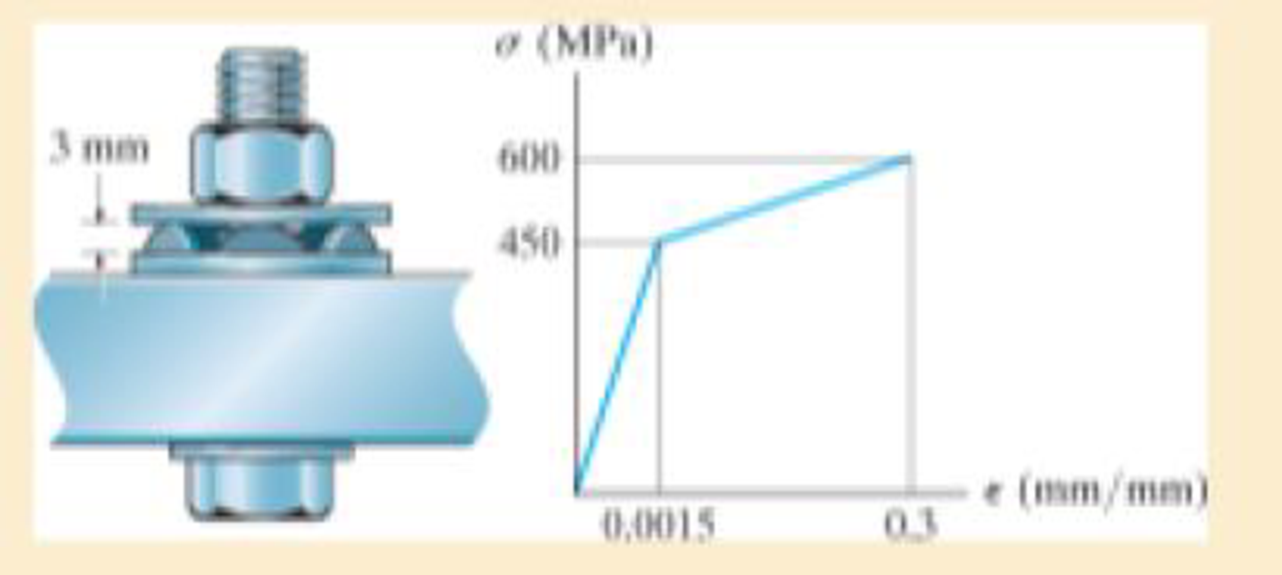
Direct tension indicators are sometimes used instead of torque wrenches to ensure that a bolt has a prescribed tension when used for connections. If a nut on the bolt is tightened so that the six 3-mm high heads of the indicator are strained 0.1 mm/mm, and leave a contact area on each head of 1.5 mm2, determine the tension in the bolt shank. The material has the stress-strain diagram shown.
Prob. 3–16
Expert Solution & Answer
Want to see the full answer?
Check out a sample textbook solution
Students have asked these similar questions
3. Direct tension indicators are sometimes used instead of torque
wrenches to ensure that a bolt has a prescribed tension when
used for connections. If a nut on the bolt is tightened so that the
six 3-mm high heads of the indicator are strained 0.1 mm/mm,
and leave a contact area on each head of 1.5 mm², determine the
tension in the bolt shank. The stress-strain diagram of the
indicator material (and bolt) is shown.
3 mm
1
σ (MPa)
600
450
0.0015
0.3
€ (mm/mm)
3–26. The thin-walled tube is subjected to an axial force
of 40 kN. If the tube elongates 3 mm and its circumference
decreases 0.09 mm, determine the modulus of elasticity,
Poisson's ratio, and the shear modulus of the tube's
material. The material behaves elastically.
40 kN
900 mm
| 10 mm
40 kN
12.5 mm
Direct tension indicators are sometimes used instead of torque wrenches to ensure that a bolt has a prescribed tension when used for connections. If a nut on the bolt is tightened so that the six 3-mm high heads of the indicator are strained 0.1 mm>mm, and leave a contact area on each head of 1.5 mm2, determine the tension in the bolt shank. The material has the stress-straindiagram is shown.
Chapter 3 Solutions
Mechanics of Materials (10th Edition)
Ch. 3.4 - Define a homogeneous material.Ch. 3.4 - Indicate the points on the stress-strain diagram...Ch. 3.4 - Define the modulus of elasticity E.Ch. 3.4 - At room temperature, mild steel is a ductile...Ch. 3.4 - Engineering stress and strain are calculated using...Ch. 3.4 - As the temperature increases the modulus of...Ch. 3.4 - A 100-mm-long rod has a diameter of 15 mm. If an...Ch. 3.4 - A bar has a length of 8 in. and cross-sectional...Ch. 3.4 - A 10-mm-diameter rod has a modulus of elasticity...Ch. 3.4 - The material for the 50-mm-long specimen has the...
Ch. 3.4 - The material for the 50-mm-long specimen has the...Ch. 3.4 - If the elongation of wire BC is 0.2 mm after the...Ch. 3.4 - A tension test was performed on a steel specimen...Ch. 3.4 - Data taken from a stress-strain test for a ceramic...Ch. 3.4 - Data taken from a stress-strain test for a ceramic...Ch. 3.4 - The stress-strain diagram for a steel alloy having...Ch. 3.4 - The stress-strain diagram for a steel alloy having...Ch. 3.4 - The stress-strain diagram for a steel alloy having...Ch. 3.4 - The rigid beam is supported by a pin at C and an...Ch. 3.4 - The rigid beam is supported by a pin at C and an...Ch. 3.4 - Acetal plastic has a stress-strain diagram as...Ch. 3.4 - The stress-strain diagram for an aluminum alloy...Ch. 3.4 - The stress-strain diagram for an aluminum alloy...Ch. 3.4 - The stress-strain diagram for an aluminum alloy...Ch. 3.4 - A bar having a length of 5 in. and cross-sectional...Ch. 3.4 - The rigid pipe is supported by a pin at A and an...Ch. 3.4 - The rigid pipe is supported by a pin at A and an...Ch. 3.4 - Direct tension indicators are sometimes used...Ch. 3.4 - The rigid beam is supported by a pin at C and an...Ch. 3.4 - The rigid beam is supported by a pin at C and an...Ch. 3.4 - The stress-strain diagram for a bone is shown, and...Ch. 3.4 - The stress-strain diagram for a bone is shown and...Ch. 3.4 - The two bars are made of a material that has the...Ch. 3.4 - The two bars are made of a material that has the...Ch. 3.4 - The pole is supported by a pin at C and an A-36...Ch. 3.4 - The bar DA is rigid and is originally held in the...Ch. 3.7 - A 100-mm-long rod has a diameter of 15 mm. If an...Ch. 3.7 - A solid circular rod that is 600 mm long and 20 mm...Ch. 3.7 - A 20-mm-wide block is firmly bonded to rigid...Ch. 3.7 - A 20-mm-wide block is bonded to rigid plates at...Ch. 3.7 - The acrylic plastic rod is 200 mm long and 15 mm...Ch. 3.7 - The plug has a diameter of 30 mm and fits within a...Ch. 3.7 - The elastic portion of the stress-strain diagram...Ch. 3.7 - The elastic portion of the stress-strain diagram...Ch. 3.7 - The brake pads for a bicycle tire are made of...Ch. 3.7 - The lap joint is connected together using a 1.25...Ch. 3.7 - The lap joint is connected together using a 1.25...Ch. 3.7 - The rubber block is subjected to an elongation of...Ch. 3.7 - The shear stress-strain diagram for an alloy is...Ch. 3.7 - A shear spring is made from two blocks of rubber,...Ch. 3 - The elastic portion of the tension stress-strain...Ch. 3 - The elastic portion of the tension stress-strain...Ch. 3 - The rigid beam rests in the horizontal position on...Ch. 3 - The wires each have a diameter of 12 in., length...Ch. 3 - The wires each have a diameter of 12 in., length...Ch. 3 - diameter steel bolts. If the clamping force in...Ch. 3 - The stress-strain diagram for polyethylene, which...Ch. 3 - The pipe with two rigid caps attached to its ends...Ch. 3 - The 8-mm-diameter bolt is made of an aluminum...Ch. 3 - An acetal polymer block is fixed to the rigid...
Knowledge Booster


Learn more about
Need a deep-dive on the concept behind this application? Look no further. Learn more about this topic, mechanical-engineering and related others by exploring similar questions and additional content below.Similar questions
- *8-16. Direct tension indicators are sometimes used instead of torque wrenches to ensure that a bolt has a prescribed tension when used for connections. If a nut on the bolt is tightened so that the six 3-mm high heads of the indicator are strained 0.1 mm/mm, and leave a contact area on each head of 1.5 mm2, determine the tension in the bolt shank. The material has the stress-strain diagram shown. a (MPa) 3 mm 600 450 (mm/mm) 0.3 0.0015arrow_forwardThe 8-mm-diameter bolt is made of an aluminum alloy. It fits through a magnesium sleeve that has an inner diameter of 12 mm and an outer diameter of 20 mm. If the original lengths of the bolt and sleeve are 80 mm and 50 mm, respectively, determine the strains in the sleeve and the bolt if the nut on the bolt is tightened so that the tension in the bolt is 8 kN. Assume the material at A is rigid. Eal = 70 GPa, Emg = 45 GPa.arrow_forward3-31. The shear stress-strain diagram for a steel alloy is shown in the figure. If a bolt having a diameter of 0.75 in. is made of this material and used in the double lap joint, determine the modulus of elasticity E and the force P required to cause the material to yield. Take v = 0.3. P= 7(ksi) 60 0.00545 Prob. 3-31 P/2 P/2 y(rad)arrow_forward
- If the bolt length is 220 mmmm and the sleeve length is 200 mmmm, determine the tension in the bolt when a force of 50 kNkN is applied to the brackets. Express your answer to three significant figures and include appropriate units. Given: The bolt AB in (Figure 1) has a diameter of 21 mmmm and passes through a sleeve that has an inner diameter of 42 mmmm and an outer diameter of 52 mmmm. The bolt and sleeve are made of A-36 steel and are secured to the rigid brackets as shown.arrow_forwardAxial loads are applied with rigid bearing plates to the solid cylindrical rods shown. If F1 = 30 kips, F2 = 15 kips, F3 = 22 kips, and F4 = 39 kips, determine the absolute value of the axial load in rod (2). A F, V (1) ▼ F, F, 1T F3 F4 F (3) Darrow_forwardPROBLEM 1/6 Determine the allowable weight that the assembly can handle if the cable AB has a working stress of 200 Mpa and cable AC has a working stress of 150 Mpa. The cable cross sectional areas are 300 mm? for cable AB and 330 mm? for cable AC. В C 50° 28° Warrow_forward
- 10. The 8-mm-diameter bolt is made of an aluminum alloy. It fits through a magnesium sleeve that has an inner diameter of 12 mm and an outer diameter of 20 mm. If the original lengths of the bolt and sleeve are 80 mm and 50 mm, respectively, determine the strains in the sleeve and the bolt if the nut on the bolt is tightened so that the tension in the bolt is 8 kN. Assume the material at A is rigid. Eal = 70 GPa, Emg = 45 GPa. 50 mm - 30 mm [Ans: Eb = 0.00227; ɛs = 0.000884]arrow_forward4. The rigid lever arm is supported by two A-36 steel wires having the same diameter of 4 mm. If a force of P = 3 kN is applied to the handle, determine the force developed in both wires and their corresponding elongations. Consider A-36 steel as an elastic-perfectly plastic material. 450 mm 150 mm 150 mm 30 300 mm B.arrow_forwardTwo vertical steel wires each 0.05 in. diameter and 48in. long support a light rod over a span of 12 in. A concentrated load of 60 lbf is then applied vertically downwards at a point 4 in. from one of the wires. Determine the load, stress and extension on each wire and the angular displacement of the rod from the horizontal assuming it does not bend. Use E = 29,000 ksi.arrow_forward
- The column is loaded with an axial force of P = 2,050 kN through a rigid endplate. Determine the deformation of the column in mm.arrow_forwardRod BD is made of steel (E = 29 × 106 psi) and is used to brace the axially compressed member ABC. The maximum force that can be developed in member BD is 0.02P. If the stress must not exceed 18 ksi and the maximum change in length of BD must not exceed 0.001 times the length of ABC, determine the smallest-diameter rod that can be used for member BD. Take P = 148 kips.The smallest-diameter rod that can be used for member BD is in.arrow_forwardAnswer the ff. The bell-crank mechanism is in equilibrium for an applied load of F1 = 19 kN applied at A. Assume a = 330mm, b = 160mm, c = 75mm, and θ = 35°. Pin B is in a double-shear connection and has a diameter of 24 mm. The bell crank has a thickness of 28 mm. Determine(a) the shear stress in pin B.(b) the bearing stress in the bell crank at B.arrow_forward
arrow_back_ios
SEE MORE QUESTIONS
arrow_forward_ios
Recommended textbooks for you
 Elements Of ElectromagneticsMechanical EngineeringISBN:9780190698614Author:Sadiku, Matthew N. O.Publisher:Oxford University Press
 Mechanics of Materials (10th Edition)Mechanical EngineeringISBN:9780134319650Author:Russell C. HibbelerPublisher:PEARSON
 Thermodynamics: An Engineering ApproachMechanical EngineeringISBN:9781259822674Author:Yunus A. Cengel Dr., Michael A. BolesPublisher:McGraw-Hill Education
 Control Systems EngineeringMechanical EngineeringISBN:9781118170519Author:Norman S. NisePublisher:WILEY
 Mechanics of Materials (MindTap Course List)Mechanical EngineeringISBN:9781337093347Author:Barry J. Goodno, James M. GerePublisher:Cengage Learning
 Engineering Mechanics: StaticsMechanical EngineeringISBN:9781118807330Author:James L. Meriam, L. G. Kraige, J. N. BoltonPublisher:WILEY
Elements Of Electromagnetics
Mechanical Engineering
ISBN:9780190698614
Author:Sadiku, Matthew N. O.
Publisher:Oxford University Press
Mechanics of Materials (10th Edition)
Mechanical Engineering
ISBN:9780134319650
Author:Russell C. Hibbeler
Publisher:PEARSON
Thermodynamics: An Engineering Approach
Mechanical Engineering
ISBN:9781259822674
Author:Yunus A. Cengel Dr., Michael A. Boles
Publisher:McGraw-Hill Education
Control Systems Engineering
Mechanical Engineering
ISBN:9781118170519
Author:Norman S. Nise
Publisher:WILEY
Mechanics of Materials (MindTap Course List)
Mechanical Engineering
ISBN:9781337093347
Author:Barry J. Goodno, James M. Gere
Publisher:Cengage Learning
Engineering Mechanics: Statics
Mechanical Engineering
ISBN:9781118807330
Author:James L. Meriam, L. G. Kraige, J. N. Bolton
Publisher:WILEY
Hand Tools; Author: UCI Media;https://www.youtube.com/watch?v=4o0tqF0jDdo;License: Standard Youtube License