
Applied Statics and Strength of Materials (6th Edition)
6th Edition
ISBN: 9780133840544
Author: George F. Limbrunner, Craig D'Allaird, Leonard Spiegel
Publisher: PEARSON
expand_more
expand_more
format_list_bulleted
Videos
Textbook Question
thumb_up100%
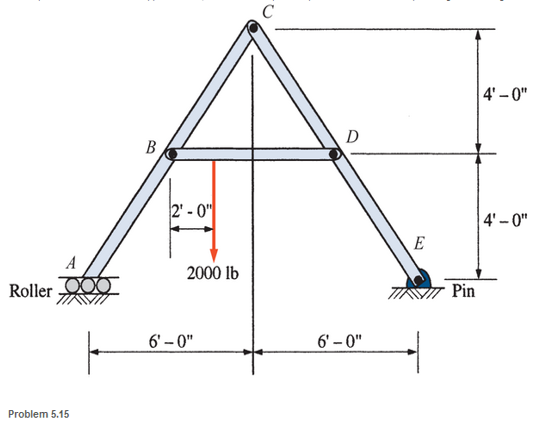
Chapter 5, Problem 5.15P
A pin-connected A-frame supports a load, as shown. Compute the pin reactions at all of the pins. Neglect the weights of the members.
Expert Solution & Answer

Learn your wayIncludes step-by-step video

schedule08:01
Students have asked these similar questions
A pin-connected crane framework is loaded and supported, as shown. The member weights are post, 700 lb; boom, 800 lb; and brace, 600 lb. These weights may be considered to be acting at the midpoint of the respective members. Calculate the pin reactions at pins A, C, D, E and at the roller B
- Draw Free-body diagram.
- Solve most simpliest way, only solving for what you are asked for.
Kindly refer to the given figure below. determine the support reactions of the points A,B and C. Note: The support A is fixed and B is and internal hinge.
The image depicts the components of a floor jack. If the hydraulic cylinder AB is intended to withstand a maximum compressive force of 37 kN, find the load L (in kN) and force (in kN) in link EF under this circumstance. Additionally, compute the pin reaction (in kN) at C. The hydraulic cylinder AB, the link EF, and the platform DF all have the necessary FBDs. Additionally, create a combined FBD for the platform DF and the member BCD.
Take note that if the figure CDFE is traced, it becomes a parallelogram. Additionally, members BCD and EF are connected to the jack's base via pins at C and E. Disregard the friction between members BCD and EF's contacting faces.
Chapter 5 Solutions
Applied Statics and Strength of Materials (6th Edition)
Ch. 5 - through 5.7 Calculate the forces in all members of...Ch. 5 - Calculate the forces in all members of the trusses...Ch. 5 - Calculate the forces in all members of the trusses...Ch. 5 - Calculate the forces in all members of the trusses...Ch. 5 - Calculate the forces in all members of the trusses...Ch. 5 - Calculate the forces in all members of the trusses...Ch. 5 - Calculate the forces in all members of the trusses...Ch. 5 - Determine the forces in members CD, DH, and HI for...Ch. 5 - Determine the forces in members BC, BE, and FE for...Ch. 5 - Determine the forces in members BC, CH, and CG in...
Ch. 5 - For the Howe roof truss shown, determine the...Ch. 5 - Determine the forces in members DE, CE, and BC in...Ch. 5 - Calculate the forces in members BC, BG, and FG for...Ch. 5 - Determine the forces in members CD, BD, BE, and CB...Ch. 5 - A pin-connected A-frame supports a load, as shown....Ch. 5 - Determine the pin reactions at pins A, B, and C in...Ch. 5 - Calculate the pin reactions at each of the pins in...Ch. 5 - A bracket is pin connected at points A, B, and D...Ch. 5 - A pin-connected frame is loaded, as shown....Ch. 5 - The cylinder shown has a mass of 500 kg. Determine...Ch. 5 - A simple frame is pin connected at points A, B,...Ch. 5 - Using the method of sections, determine the forces...Ch. 5 - Using the method of sections, determine the forces...Ch. 5 - through 5.31 Calculate the forces in all members...Ch. 5 - Calculate the forces in all members of the trusses...Ch. 5 - Calculate the forces in all members of the trusses...Ch. 5 - Calculate the forces in all members of the trusses...Ch. 5 - Calculate the forces in all members of the trusses...Ch. 5 - Calculate the forces in all members of the trusses...Ch. 5 - Calculate the forces in all members of the trusses...Ch. 5 - Calculate the forces in all members of the trusses...Ch. 5 - For Problems 5.32 through 5.38, calculate the...Ch. 5 - For Problem 5.32 through 5.38, Calculate the...Ch. 5 - For Problems 5.32 through 5.38, calculate the...Ch. 5 - For Problems 5.32 through 5.38, calculate the...Ch. 5 - For Problem 5.32 through 5.38 , Calculate the...Ch. 5 - For Problems 5.32 through 5.38, calculate the...Ch. 5 - For Problems 5.32 through 5.38, calculate the...Ch. 5 - A pin-connected crane framework is loaded and...Ch. 5 - Calculate the pin reactions at pins A, B, and D in...Ch. 5 - Determine the pin reactions at pins A, B, and C in...Ch. 5 - The wall bracket shown is pin-connected at points...Ch. 5 - Calculate the pin reactions at each of the pins in...Ch. 5 - The A-frame shown is pin-connected at A,B,C, and...Ch. 5 - The tongs shown are used to grip an object. For an...Ch. 5 - A toggle joint is a mechanism by which a...Ch. 5 - In the toggle joint of Problem 5.46 , assume that...Ch. 5 -
Additional Engineering Textbook Solutions
Find more solutions based on key concepts
F416. Determine the magnitude of the moment of the force about the y axis. F = {30i 20j + 50k} N
INTERNATIONAL EDITION---Engineering Mechanics: Statics, 14th edition (SI unit)
What parts are included in the vehicle chassis?
Automotive Technology: Principles, Diagnosis, and Service (5th Edition)
A loading causes the mamber to deform into the dashed shape. Explain how to determine the normal strains CD and...
Mechanics of Materials
ICA 8-8
If the density of sodium is 98 kilograms per cubic meter [kg/m3], what is this in slugs per gallon [slu...
Thinking Like an Engineer: An Active Learning Approach (3rd Edition)
Figure 7.21 shows a pump delivering 840L/min of crude oil (sg = 0.85 ) from an underground storage drum to the ...
Applied Fluid Mechanics (7th Edition)
1.1 What is the difference between an atom and a molecule? A molecule and a crystal?
Manufacturing Engineering & Technology
Knowledge Booster


Learn more about
Need a deep-dive on the concept behind this application? Look no further. Learn more about this topic, mechanical-engineering and related others by exploring similar questions and additional content below.Similar questions
- Compute the magnitude of the pin reaction at B. Neglect the weights of the structural members.arrow_forwardThe figure shows the FBD of a portion of the space truss shown in Fig. P5.25. Use this FBD to find the force in member BD.arrow_forwardCompute the magnitudes of the reactions at pin A and the roller at D. Neglect the weight of the body.arrow_forward
- 1- Calculate all the rod forces in the truss system shown in the figure by using the knot method.arrow_forwardDraw the free-body diagram for the following problem. The rod shown.arrow_forwardConsider the pin connected frame. Compute for the reactions at the supports and the reactions at the jointsarrow_forward
- Calculate the support reactions at pin B and roller A that result from the applied loads shown. You must show a FBD drawn with a straight edge and all unknowns must be labeledand the same labels used in your calculations.arrow_forwardDraw the FBD for bar BCD The connections at A and B are ball-and-socket joints, C is a slider bearing, and D is a thrust bearing. Assume that the weights of members are negligible and recognize that AB is a two-force member How many unknowns appear on the FBD? Solve for the unknowns.arrow_forwardFigure 1: For the frame shown, determine the magnitude of the pin reaction at B. Neglect the weight of the frame. (2 decimal point, indicate the answer in kN. Ex: 3.87kN just encode 3.78)arrow_forward
- Compute for the external reactions for all members of the frame shown. Please solve the following: Vertical Reaction at C = 624 (WRONG) Horizontal Reaction at C = 400 (WRONG) Horizontal Reaction at B = 400 (WRONG) Horizontal Reaction at D = 400 (WRONG)arrow_forwardCompute for the external reactions for all members of the frame shown. Please solve the following: Vertical Reaction at A Horizontal Reaction at A Vertical Reaction at E Vertical Reaction at D Vertical Reaction at B Vertical Reaction at C Horizontal Reaction at C Horizontal Reaction at B Horizontal Reaction at Darrow_forwardA simple beam is subjected to vertical concentrated and uniformly distributed loads shown below. The beam is pin supported at A and roller supported at B. Calculate the reactions at each support. Neglect the weight of the beamarrow_forward
arrow_back_ios
SEE MORE QUESTIONS
arrow_forward_ios
Recommended textbooks for you
 International Edition---engineering Mechanics: St...Mechanical EngineeringISBN:9781305501607Author:Andrew Pytel And Jaan KiusalaasPublisher:CENGAGE L
International Edition---engineering Mechanics: St...
Mechanical Engineering
ISBN:9781305501607
Author:Andrew Pytel And Jaan Kiusalaas
Publisher:CENGAGE L
Material Science, Phase Diagrams, Part 1; Author: Welt der Werkstoffe;https://www.youtube.com/watch?v=G83ZaoB3XCc;License: Standard Youtube License