
Applied Statics and Strength of Materials (6th Edition)
6th Edition
ISBN: 9780133840544
Author: George F. Limbrunner, Craig D'Allaird, Leonard Spiegel
Publisher: PEARSON
expand_more
expand_more
format_list_bulleted
Concept explainers
Videos
Textbook Question
Chapter 5, Problem 5.38SP
For Problems 5.32  through 5.38,
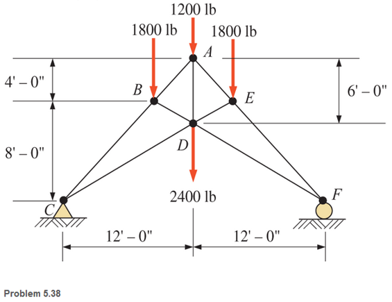
  calculate the forces in the indicated members of the trusses shown. Use the method of sections.
5.38 Members BC, CD, and AD.
Expert Solution & Answer
Want to see the full answer?
Check out a sample textbook solution
Students have asked these similar questions
The Warren truss loaded as shown in the figure is supported by a roller at C and a hinge at G. By the method of sections, compute the force in the members BC, DF, and CE.
Determine the member forces for all members in each truss shown using the method on joints. Remember to list each member force as either tension or compression.
Calculate the forces in member CF of the truss and state the member is in tension or compression using the method of sections
Chapter 5 Solutions
Applied Statics and Strength of Materials (6th Edition)
Ch. 5 - through 5.7 Calculate the forces in all members of...Ch. 5 - Calculate the forces in all members of the trusses...Ch. 5 - Calculate the forces in all members of the trusses...Ch. 5 - Calculate the forces in all members of the trusses...Ch. 5 - Calculate the forces in all members of the trusses...Ch. 5 - Calculate the forces in all members of the trusses...Ch. 5 - Calculate the forces in all members of the trusses...Ch. 5 - Determine the forces in members CD, DH, and HI for...Ch. 5 - Determine the forces in members BC, BE, and FE for...Ch. 5 - Determine the forces in members BC, CH, and CG in...
Ch. 5 - For the Howe roof truss shown, determine the...Ch. 5 - Determine the forces in members DE, CE, and BC in...Ch. 5 - Calculate the forces in members BC, BG, and FG for...Ch. 5 - Determine the forces in members CD, BD, BE, and CB...Ch. 5 - A pin-connected A-frame supports a load, as shown....Ch. 5 - Determine the pin reactions at pins A, B, and C in...Ch. 5 - Calculate the pin reactions at each of the pins in...Ch. 5 - A bracket is pin connected at points A, B, and D...Ch. 5 - A pin-connected frame is loaded, as shown....Ch. 5 - The cylinder shown has a mass of 500 kg. Determine...Ch. 5 - A simple frame is pin connected at points A, B,...Ch. 5 - Using the method of sections, determine the forces...Ch. 5 - Using the method of sections, determine the forces...Ch. 5 - through 5.31 Calculate the forces in all members...Ch. 5 - Calculate the forces in all members of the trusses...Ch. 5 - Calculate the forces in all members of the trusses...Ch. 5 - Calculate the forces in all members of the trusses...Ch. 5 - Calculate the forces in all members of the trusses...Ch. 5 - Calculate the forces in all members of the trusses...Ch. 5 - Calculate the forces in all members of the trusses...Ch. 5 - Calculate the forces in all members of the trusses...Ch. 5 - For Problems 5.32 through 5.38, calculate the...Ch. 5 - For Problem 5.32 through 5.38, Calculate the...Ch. 5 - For Problems 5.32 through 5.38, calculate the...Ch. 5 - For Problems 5.32 through 5.38, calculate the...Ch. 5 - For Problem 5.32 through 5.38 , Calculate the...Ch. 5 - For Problems 5.32 through 5.38, calculate the...Ch. 5 - For Problems 5.32 through 5.38, calculate the...Ch. 5 - A pin-connected crane framework is loaded and...Ch. 5 - Calculate the pin reactions at pins A, B, and D in...Ch. 5 - Determine the pin reactions at pins A, B, and C in...Ch. 5 - The wall bracket shown is pin-connected at points...Ch. 5 - Calculate the pin reactions at each of the pins in...Ch. 5 - The A-frame shown is pin-connected at A,B,C, and...Ch. 5 - The tongs shown are used to grip an object. For an...Ch. 5 - A toggle joint is a mechanism by which a...Ch. 5 - In the toggle joint of Problem 5.46 , assume that...Ch. 5 -
Knowledge Booster


Learn more about
Need a deep-dive on the concept behind this application? Look no further. Learn more about this topic, mechanical-engineering and related others by exploring similar questions and additional content below.Similar questions
- Problem 5.2 Calculate the forces in all members of the trusses shown using the method of joints. Please show all work and units. Thanksarrow_forwardUse the method of Sections To Compute The Internal Axial Forces In Members CD, CE, And EF.arrow_forwardFind the forces in members EF, KL, and GL for the Fink truss shown. Use method of sections.arrow_forward
- Find the forces in members EF, KL, and GL for the Fink truss shown. Answer using method of section.arrow_forwardIdentify the zero force members in the following truss.arrow_forwardProblem 7 Compute the reaction forces in B and D. Hint: in this case, since you have to determine the external reactions only, you can consider the truss as a single rigid body 4.5 m 4.5 m B 2.8 m A 8.4 kN 8.4 kNarrow_forward
- Calculate the forces in members BC,BE and CE, of the loaded truss All triangles are isosceles 6 kN B 6m E 6m 8 kNarrow_forwardIdentify all the zero-force members in the four trusses shown. (No need to draw the given trusses)arrow_forwardCalculate the forces in members AB, BG, and GF using the method of section.arrow_forward
- In the Fink truss shown in below with symmetrical loadings, BC and EF are perpendicular to the inclined members at their mid points. Use the method of joints to determine the forces in each member. Hint : Solve first for the reaction at A and G.arrow_forwardDetermine the forces in members BC, CF, and EF of the stairs truss shown in Figure 5.State whether the members are intension or compression.arrow_forwardUsing the method of joints, calculate the force in each member of the truss shown. State whether each member is in tension or compression.arrow_forward
arrow_back_ios
SEE MORE QUESTIONS
arrow_forward_ios
Recommended textbooks for you
 International Edition---engineering Mechanics: St...Mechanical EngineeringISBN:9781305501607Author:Andrew Pytel And Jaan KiusalaasPublisher:CENGAGE L
International Edition---engineering Mechanics: St...
Mechanical Engineering
ISBN:9781305501607
Author:Andrew Pytel And Jaan Kiusalaas
Publisher:CENGAGE L
Engineering Basics - Statics & Forces in Equilibrium; Author: Solid Solutions - Professional Design Solutions;https://www.youtube.com/watch?v=dQBvQ2hJZFg;License: Standard YouTube License, CC-BY