
Concept explainers
Videos
Solve for vo(t) in the circuit of Fig. 10.91 using the superposition principle.
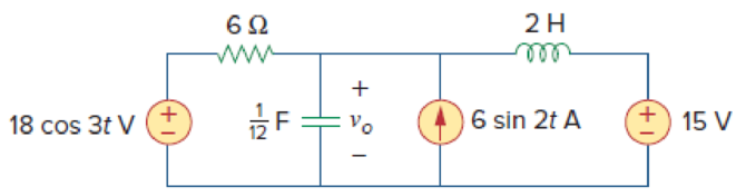
Figure 10.91
Calculate the voltage
Answer to Problem 46P
The value of voltage
Explanation of Solution
Given data:
Refer to Figure 10.91 in the textbook.
Formula used:
Write the expression to calculate impedance of the inductor.
Here,
Write the expression to calculate impedance of the capacitor.
Here,
Write the general representation of sinusoidal cosine function.
Here,
Write the general expression to phasor transform of sinusoidal function from time domain to frequency domain.
Here,
Write the polar form representation of frequency domain.
Write the general representation of sinusoidal sine function.
Here,
Write the general expression to phasor transform of sinusoidal function from time domain to frequency domain.
Here,
Write the polar form representation of frequency domain.
Calculation:
Let
Consider that
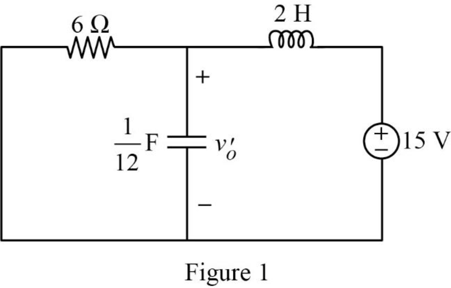
The capacitor acts like an open circuit for DC source. Therefore, the entire source voltage will appear across the capacitor.
Consider that
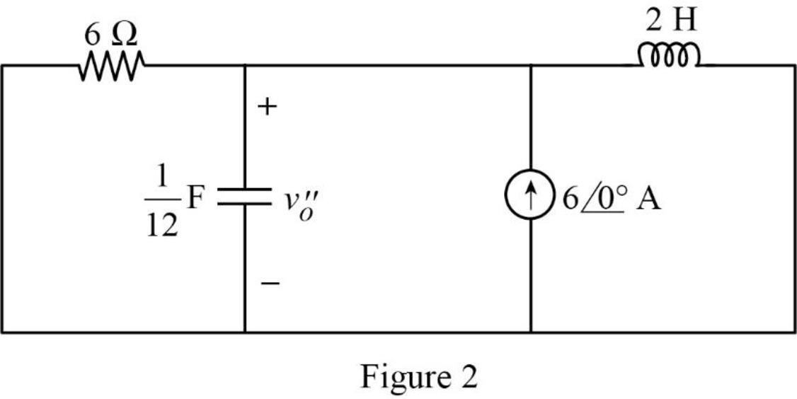
Comparing
Substitute
Substitute
Substitute
The frequency domain representation of figure 2 is shown in Figure 3.
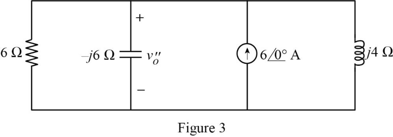
In Figure 3, the reduce the parallel combination of
The reduced circuit is shown in Figure 4.
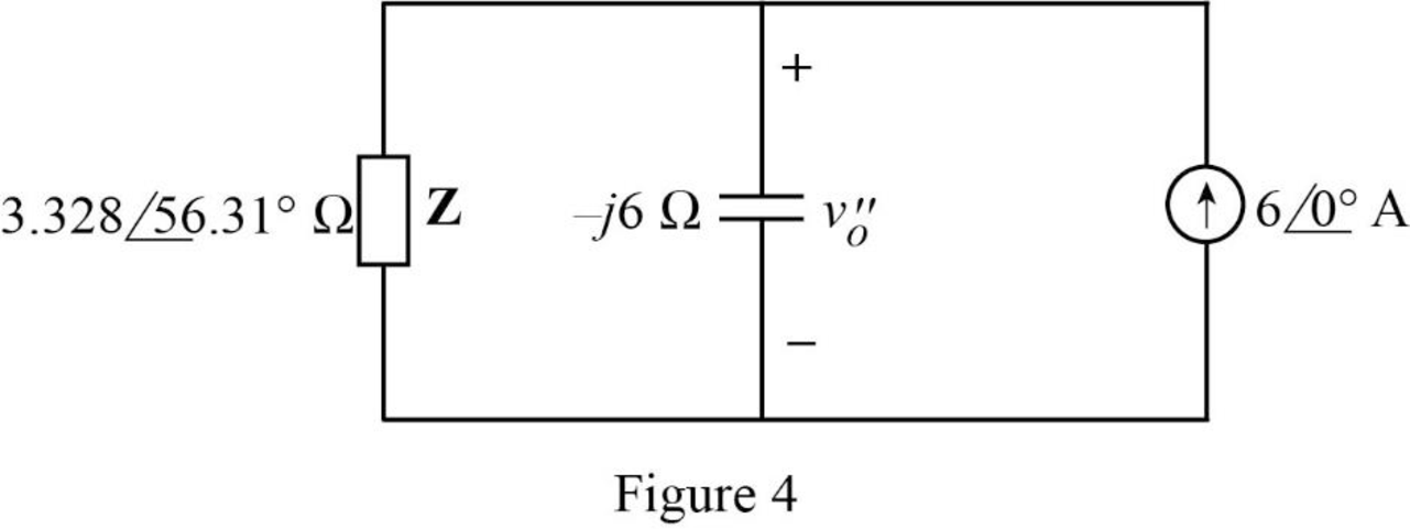
From Figure 4, calculate the current flows through the capacitor using current division rule.
Write the expression to calculate the voltage
Substitute
Write the time domain representation of voltage
Consider that
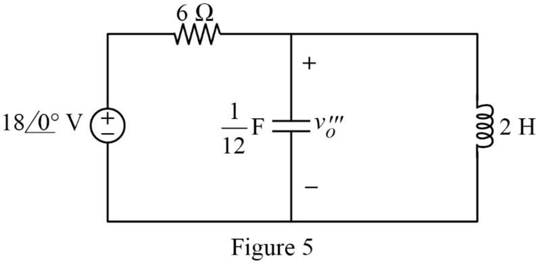
Comparing
Substitute
Substitute
Substitute
The frequency domain representation of figure 5 is shown in Figure 6.
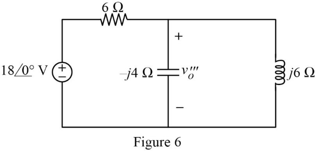
Apply Kirchhoff’s current law at node
Simplify the equation as follows.
Write the time domain representation of voltage
Write the expression for
Substitute
Conclusion:
Thus, the value of voltage
Want to see more full solutions like this?
Chapter 10 Solutions
Fundamentals of Electric Circuits
Additional Engineering Textbook Solutions
Principles Of Electric Circuits
Principles and Applications of Electrical Engineering
Electronics Fundamentals: Circuits, Devices & Applications
Electrical Engineering: Principles & Applications (7th Edition)
Introductory Circuit Analysis (13th Edition)
Microelectronics: Circuit Analysis and Design


- The oscillator circuit in Fig. 10.134 uses an ideal op amp. (a) Calculate the minimum value of R, that will cause oscillation to occur. (b) Find the frequency of oscillation. 1 M2 100 k2 ww R. 10 μΗ 2 nF 10 k2 wwarrow_forwardDetermine the Thevenin equivalent of the circuit in Fig. 10. 27 as seen from terminals a-b. 82 j42 ll ww o a -j22 5/0° A 0.2V 42arrow_forward10. R equivalent AO R, R, R, 300 BOarrow_forward
- ITORS 3 μF 6 μF 0.2 μF HE 7 μF 24 CT SECTION 10.13 Capacitors in Series and Parallel 44. Find the total capacitance C, between points a and b of the circuits of Fig. 10.104. 60 pF O a 30 pF CT b 20 pF (b) # 10 pFarrow_forward10:45 1 .III 5G Done Series Parallel Practice Problems 1 of 7 Series/Parallel Circuits Practice Problems For each circuit provided, fully solve and complete the associated table. 1. 12 GOV RS 2000 R4 3000 R3 350 R(Q) V(v) I(A) P(W) 22222 300 300 35 15 200 Total R(Q) V(v) I(A) P(W)arrow_forwardDetermine the Norton equivalent of the circuit in Fig. 10.30 as seen from terminals a-b. Use the equivalent to find I ww IA -130 wwH ww 10A 10/0 V O 290 Aarrow_forward
- 3. Referring to the circuit shown below. If v(t) is 120 cos (1000t-30°) V, determine the following: (a) Inductor current (b) The voltage between terminals a and b, Vab a v(t) 302 -WW- 6Ω 8mH Note: Express your final answer in polar form. www 4Ω b 125μFarrow_forwardPRACTICE PROBLEM 10.7 Find I, in the circuit of Fig. 10.19 using the concept of source transfor- mation. 4/90° A 292 jlQ wwwm Answer: 3.288/99.46° A. 4Ω -j3 92 j5 92 Figure 10.19 For Practice Prob. 10.7. 192 -j2 92arrow_forwardEvaluate F(4). f(t)=sin(2t)cos(2t) Round-off to 4 decimal places. Answer: 0.0625arrow_forward
- Determine the Thevenin equivalent of the circuit in Fig. 10.27 as seen from the terminals a-b.arrow_forwardа). maximum power transfer in the circuit below What is maximum power transfer, hence determine RL for RL 4 kN 6 kN 3 kn 3 V 2 mAarrow_forwardCalculate Vo in the circuit of Fig. 10.15 using the superposition theorem. 8Ω ww 50 sin 5t V + 0.2 F 1 H 4 cos 10t A llarrow_forward
 Introductory Circuit Analysis (13th Edition)Electrical EngineeringISBN:9780133923605Author:Robert L. BoylestadPublisher:PEARSON
 Delmar's Standard Textbook Of ElectricityElectrical EngineeringISBN:9781337900348Author:Stephen L. HermanPublisher:Cengage Learning
 Programmable Logic ControllersElectrical EngineeringISBN:9780073373843Author:Frank D. PetruzellaPublisher:McGraw-Hill Education
 Fundamentals of Electric CircuitsElectrical EngineeringISBN:9780078028229Author:Charles K Alexander, Matthew SadikuPublisher:McGraw-Hill Education
 Electric Circuits. (11th Edition)Electrical EngineeringISBN:9780134746968Author:James W. Nilsson, Susan RiedelPublisher:PEARSON
 Engineering ElectromagneticsElectrical EngineeringISBN:9780078028151Author:Hayt, William H. (william Hart), Jr, BUCK, John A.Publisher:Mcgraw-hill Education,