
Videos
Consider the circuit in Figure P12.26. The input resistance of the op-amp is
where
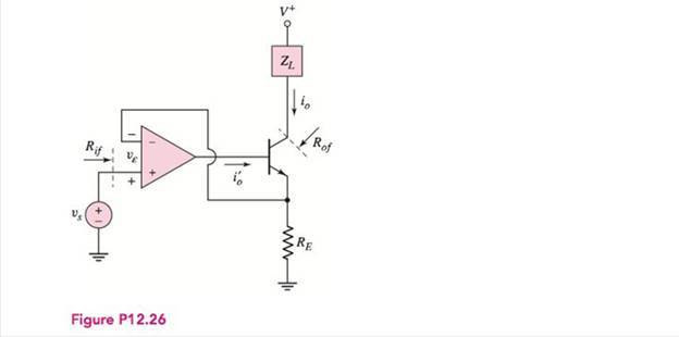
Figure P12.26
Want to see the full answer?
Check out a sample textbook solution
Chapter 12 Solutions
Microelectronics: Circuit Analysis and Design


- Project # 3 (Use a FET op-amp) You’ve been working with an implementation team to build the following components of a system: The system consists of a DC power supply, filters, instrumentation amplifier, one-state system and A/D converter. Build an AC/DC dual power supply circuit that draws a 55Vp-p sinusoidal voltage, to provide a dc output voltage of +10 V. Find the proper data sheet of the IC regulator and specify ranges of output current and voltage. Full analysis of voltages and currents should be included. What modifications would you recommend to draw more current while maintaining same output voltage? Build a 4th order Butterworth LP filters that cover a signal range 10kHz and a gain of 100V/V each. Use C = 0.01µF with proper values of R’s. Record your findings and include plots (magnitude and phase. Calculate the roll-off of the filter. Build an instrumentation amplifier having a differential gain of 50V/V. Choose the right differential input and common input signals to…arrow_forwardFeedback: 2. An ideal series-shunt feedback amplifier has Rs negligibly small. If Vi = 100mV, Vfb = 99mV, and Vo= 5V determine: a. Av, ß, Avf (including the units) b. Rif, Rof if Ri= 5 Kohm & Ro = 4 Kohm.arrow_forwardUsing Mason's gain formula calculate the closed-loop transfer function for the system described by the following equations: Y2= Y1– H1Y3– H3Y5 Y3 = G1Y2– H4Y4 Y4 = G2Y3 + G4Y2 %3D Y5 = G3Y4 Y6 = Y5arrow_forward
- 7 7 76% Q4. Figure 4 shows a circult diagram of the Wien-bridge oscillator. ASsume that the amplifier employed is an ideal op-amp. a) State the Barkhausen criterion for sustained oscillation. b) Explain briefly how the phase shift requirement for sustained oscillation is met in this circuit. c) The feedback ratio of the circuit shown in Figure 4 is given by, %3D 3R +j(2afCR-C) 27/ Derive the expression for the oscillation frequency, f. R. Figure 4 Colpitts oscillator - 7x-arrow_forwardPROBLEM NUMBER 1 For the collector feedback configuration, determine the following: a. IB b. lc C. Vc R1 www 5100 IB VCC 12V R2 470kQ Hu R3 >210kΩ VC Ic Q1 2N2712 hFE=250arrow_forwardAn ideal series-shunt feedback amplifier has Rs negligibly small. If Vi= 100mV, Vfb = 99mV, and Vo= 5V determine: a. Av, B, Avf (including the units) b. Rif, Rof if Ri= 5 Kohm & Ro = 4 Kohm.arrow_forward
- An ideal shunt-shunt feedback amplifier has Rs =∞. If li = 100 microAmp, I f = 99 microAmp and Vo = 5V determine: a. Az, Bg and Azf, (including the units) b. Rif & Rof if Ri= 5 Kohm & Ro = 4 Kohm.arrow_forward3. An ideal shunt-shunt feedback amplifier has Rs =∞. If li= 100 microAmp, I fb = 99 microAmp and Vo = 5V determine: a. Az, Bg and Azf, (including the units) b. Rif & Rof if Ri= 5 Kohm & Ro = 4 Kohm.arrow_forwardFeedback:2. An ideal series-shunt feedback amplifier has Rs negligibly small. If Vi = 100mV, Vfb =99mV, and Vo= 5V determine:a. Av , β, Avf (including the units)b. Rif, Rof if Ri = 5 Kohm & Ro = 4 Kohm.arrow_forward
- a) Negative feedback circuits such as the Schmitt trigger are used to solve noisy scenarios in comparator circuit applications. Using circuit diagrams and waveforms, explain clearly how this is achieved. b) An LM35 temperature sensor has the following transfer function: Vout 10mV °C x Temp (°C) Design an electronic circuit to turn on an LED rated at 5V whenever the temperature falls below 85°C. The circuit should use a comparator, a few resistors and the LM35 temperature sensor. You should demonstrate by calculation and by simulation in multisim or proteus that your circuit works correctly. Only screenshots are required for simulation no files needed.arrow_forward8. If the CMRR of a practical op-amp is 108 dB and the common mode gain is 0.4, the open loop gain is: a) 100000 b) 200000 c) 400000 d) 500000arrow_forward3. Prove that Rg SB(Rc + Rp) is the required condition for an optimum design of the voltage-feedback circuit.arrow_forward
 Introductory Circuit Analysis (13th Edition)Electrical EngineeringISBN:9780133923605Author:Robert L. BoylestadPublisher:PEARSON
 Delmar's Standard Textbook Of ElectricityElectrical EngineeringISBN:9781337900348Author:Stephen L. HermanPublisher:Cengage Learning
 Programmable Logic ControllersElectrical EngineeringISBN:9780073373843Author:Frank D. PetruzellaPublisher:McGraw-Hill Education
 Fundamentals of Electric CircuitsElectrical EngineeringISBN:9780078028229Author:Charles K Alexander, Matthew SadikuPublisher:McGraw-Hill Education
 Electric Circuits. (11th Edition)Electrical EngineeringISBN:9780134746968Author:James W. Nilsson, Susan RiedelPublisher:PEARSON
 Engineering ElectromagneticsElectrical EngineeringISBN:9780078028151Author:Hayt, William H. (william Hart), Jr, BUCK, John A.Publisher:Mcgraw-hill Education,