
Fundamentals of Electric Circuits
6th Edition
ISBN: 9780078028229
Author: Charles K Alexander, Matthew Sadiku
Publisher: McGraw-Hill Education
expand_more
expand_more
format_list_bulleted
Concept explainers
Videos
Textbook Question
Chapter 13.5, Problem 9PP
Find Vo in the circuit of Fig. 13.40.
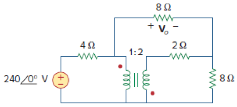
Figure 13.40
For Practice Prob. 13.9.
Expert Solution & Answer
Want to see the full answer?
Check out a sample textbook solution
Students have asked these similar questions
13.11 Find the value of Rf necessary to produce an output that is five times the sum of the inputs in the circuit
below:
R;
R1
+I Vo W
22 kl
22 k2
R2
+1.8 VoW
VOUT
22 kl
Example:
For the circuit shown in Figure below find;
a) The value of R1 for maximum power transfer.
b) The maximum output power.
( Ans. 9 Ω, 13.44W)
R,
R3
R4
2Ω a
R2
12 Q
E
R
12V
2A
b
Solution:
For the circuit shown in Figure below find;
a) The value of RL for maximum power transfer.
b) The maximum output power.
(Ans. 9 Ω, 13.44W)
R
R3
3Ω
R4
2Ω a
R2
12 ΩΣ
E
RL
12V
2A
Chapter 13 Solutions
Fundamentals of Electric Circuits
Ch. 13.2 - Determine the voltage Vo in the circuit of Fig....Ch. 13.2 - Determine the phasor currents I1 and I2 in the...Ch. 13.3 - Prob. 3PPCh. 13.4 - Find the input impedance of the circuit in Fig....Ch. 13.4 - For the linear transformer in Fig. 13.26(a), find...Ch. 13.4 - Solve the problem in Example 13.1 (see Fig. 13.9)...Ch. 13.5 - The primary current to an ideal transformer rated...Ch. 13.5 - In the ideal transformer circuit of Fig. 13.38,...Ch. 13.5 - Find Vo in the circuit of Fig. 13.40. Figure 13.40...Ch. 13.6 - Refer to Fig. 13.43. If the two-winding...
Ch. 13.6 - In the autotransformer circuit of Fig. 13.45, find...Ch. 13.7 - Prob. 12PPCh. 13.8 - Prob. 13PPCh. 13.9 - Refer to Fig. 13.61. Calculate the turns ratio...Ch. 13.9 - Calculate the turns ratio of an ideal transformer...Ch. 13.9 - In Example 13.17, if the eight 100-W bulbs are...Ch. 13 - Refer to the two magnetically coupled coils of...Ch. 13 - Prob. 2RQCh. 13 - Prob. 3RQCh. 13 - Prob. 4RQCh. 13 - The ideal transformer in Fig. 13.70(a) has N2/N1 =...Ch. 13 - Prob. 6RQCh. 13 - A three-winding transformer is connected as...Ch. 13 - Prob. 8RQCh. 13 - Prob. 9RQCh. 13 - Prob. 10RQCh. 13 - For the three coupled coils in Fig. 13.72,...Ch. 13 - Using Fig. 13.73, design a problem to help other...Ch. 13 - Two coils connected in series-aiding fashion have...Ch. 13 - (a) For the coupled coils in Fig. 13.74(a), show...Ch. 13 - Two coils are mutually coupled, with L1 = 50 mH,...Ch. 13 - Given the circuit shown in Fig. 13.75, determine...Ch. 13 - For the circuit in Fig. 13.76, find Vo. Figure...Ch. 13 - Find v(t) for the circuit in Fig. 13.77.Ch. 13 - Prob. 9PCh. 13 - Find vo in the circuit of Fig. 13.79. Figure 13.79...Ch. 13 - Use mesh analysis to find ix in Fig. 13.80, where...Ch. 13 - Determine the equivalent Leq in the circuit of...Ch. 13 - For the circuit in Fig. 13.82, determine the...Ch. 13 - Obtain the Thevenin equivalent circuit for the...Ch. 13 - Find the Norton equivalent for the circuit in Fig....Ch. 13 - Obtain the Norton equivalent at terminals a-b of...Ch. 13 - In the circuit of Fig. 13.86, ZL is a 15-mH...Ch. 13 - Find the Thevenin equivalent to the left of the...Ch. 13 - Determine an equivalent T-section that can be used...Ch. 13 - Determine currents I1, I2, and I3 in the circuit...Ch. 13 - Prob. 21PCh. 13 - Find current Io in the circuit of Fig. 13.91.Ch. 13 - Let is = 5 cos (100t) A. Calculate the voltage...Ch. 13 - In the circuit of Fig. 13.93, (a) find the...Ch. 13 - Prob. 25PCh. 13 - Find Io in the circuit of Fig. 13.95. Switch the...Ch. 13 - Find the average power delivered to the 50-...Ch. 13 - In the circuit of Fig. 13.97, find the value of X...Ch. 13 - Prob. 29PCh. 13 - (a) Find the input impedance of the circuit in...Ch. 13 - Using Fig. 13.100, design a problem to help other...Ch. 13 - Two linear transformers are cascaded as shown in...Ch. 13 - Determine the input impedance of the air-core...Ch. 13 - Using Fig. 13.103, design a problem to help other...Ch. 13 - Find currents I1, I2, and I3 in the circuit of...Ch. 13 - As done in Fig. 13.33, obtain the relationships...Ch. 13 - A 2402,400-V rms step-up ideal transformer...Ch. 13 - Design a problem to help other students better...Ch. 13 - A 1,200240-V rms transformer has impedance on the...Ch. 13 - The primary of an ideal transformer with a turns...Ch. 13 - Given I2 = 2 A, determine the value of Is in Fig....Ch. 13 - For the circuit in Fig. 13.107, determine the...Ch. 13 - Obtain V1 and V2 in the ideal transformer circuit...Ch. 13 - In the ideal transformer circuit of Fig. 13.109,...Ch. 13 - For the circuit in Fig. 13.110, find the value of...Ch. 13 - (a) Find I1 and I2 in the circuit of Fig. 13.111...Ch. 13 - Prob. 47PCh. 13 - Using Fig. 13.113, design a problem to help other...Ch. 13 - Find current ix in the ideal transformer circuit...Ch. 13 - Prob. 50PCh. 13 - Use the concept of reflected impedance to find the...Ch. 13 - For the circuit in Fig. 13.117, determine the...Ch. 13 - Refer to the network in Fig. 13.118. (a) Find n...Ch. 13 - A transformer is used to match an amplifier with...Ch. 13 - For the circuit in Fig. 13.120, calculate the...Ch. 13 - Find the power absorbed by the 100- resistor in...Ch. 13 - For the ideal transformer circuit of Fig. 13.122...Ch. 13 - Determine the average power absorbed by each...Ch. 13 - In the circuit of Fig. 13.124, let vs = 165...Ch. 13 - Refer to the circuit in Fig. 13.125 on the...Ch. 13 - For the circuit in Fig. 13.126, find Il, I2, and...Ch. 13 - For the network in Fig. 13.127, find: (a) the...Ch. 13 - Find the mesh currents in th circuit of Fig....Ch. 13 - For the circuit in Fig. 13.129. find the turns...Ch. 13 - Calculate the average power dissipated by the 20-...Ch. 13 - Design a problem to help other students better...Ch. 13 - An autotransformer with a 40 percent tap is...Ch. 13 - In the ideal autotransformer of Fig. 13.131,...Ch. 13 - In the circuit of Fig. 13.131, N1 = 190 turns and...Ch. 13 - In the ideal transformer circuit shown in Fig....Ch. 13 - When individuals travel, their electrical...Ch. 13 - In order to meet an emergency, three single-phase...Ch. 13 - Figure 13.135 on the next page shows a three-phase...Ch. 13 - Consider the three-phase transformer shown in Fig....Ch. 13 - A balanced three-phase transformer bank with the...Ch. 13 - Using Fig. 13.138, design a problem to help other...Ch. 13 - The three-phase system of a town distributes power...Ch. 13 - Use PSpice or MultiSim to determine the mesh...Ch. 13 - Use PSpice or MultiSim to find I1, I2, and I3 in...Ch. 13 - Prob. 80PCh. 13 - Use PSpice or MultiSim to find I1, I2, and I3 in...Ch. 13 - A stereo amplifier circuit with ail output...Ch. 13 - A transformer having 2,400 turns on the primary...Ch. 13 - A radio receiver has an input resistance of 300 ....Ch. 13 - A step-down power transformer with a turns ratio...Ch. 13 - A 240120-V rms power transformer is rated at 10...Ch. 13 - A 4-kVA, 2,400240-V rms transformer has 250 turns...Ch. 13 - A 25,000240-V rms distribution transformer has a...Ch. 13 - A 4,800-V rms transmission line feeds a...Ch. 13 - A four-winding transformer (Fig. 13.146) is often...Ch. 13 - A 440/110-V ideal transformer can be connected to...Ch. 13 - Ten bulbs in parallel are supplied by a 7,200120-V...
Knowledge Booster


Learn more about
Need a deep-dive on the concept behind this application? Look no further. Learn more about this topic, electrical-engineering and related others by exploring similar questions and additional content below.Similar questions
- Determine the value of the Current 13. +1 12 V + - www 892 O A. 0.44 Amps OB. 1.05 Amps OC. 0.15 Amps O D. 0.45 Amps OE. 0.35 Amps + 9 V - www 20 92 13arrow_forwardA power suppply having 220 V AC input and two fixed outputs as 10 V DC and 20 V DC is requested from you. For this purpose, a transformer with 220 V AC input / 15 V AC output, some capacitors, some silicon diodes, and zener diodes are presented. a) Design your power supply and point out DC voltage outputs b) Explain the operation of the network and all the components used in the design c) Calculate and plot input and output signals of the network Hint: For design, remember clipper, clamper, rectifier,voltage multiplier and zener circuitsarrow_forwardAs shown in the circuit below, a transformer is used to match an amplifier with an 8-ohm load. The Thevenin equivalent of the amplifier is Vth = 10 V, Zth = 128 ohms. What is the required turns ratio n for maximum power transfer? 1:n Amplifier circuit ell 892arrow_forward
- O 50 15. Why should design our circuits to operate below the SRF of electrical elements? to increase the gain to make the circuit simple None of them to reduce the power used in the circuit. to avoid the unexpected behavoir Page 1 of 1 Submit Clear formarrow_forwardA step down chopper has input DC voltage of 200V and a load of R=10nin series with L= 80 mH. if the load current varies linearly between 12 amps and 16 amps, find the time ratio Ton / Toff of this chopper.arrow_forwardQ13. Find Req at terminals a-b in Figure Q13. 70 Ω ao 30 Ω 40 Ω 60N bo 20Ω Figure Q13arrow_forward
- 2. Draw a circuit schematic indicating how you will connect your DC power supply to provide +8 V, -8 V and a 0 V common. 3. Draw a circuit schematic (including IC pin numbers and bypass capacitors) for Part A, D, E being sure to note which resistor values you will be using (this may require calculations in advance). 4. Design matrix for digital-to-analog converterarrow_forwardA Pulley is an example of active amplifier. Select one: O a. True O b. False A sinusoidal voltage v = (10 sin 377t) V rm.s is applied to a resistor of 50 Q. The avera Select one: ONone of the Answers O0.2 W O20 W 2Warrow_forwardElectronic Circuit Lab Discussion:- 1. If the input voltage 32VP.P and f=50HZ, sketch the output of the circuit shown below. 10kn 10k 3 V 4 V 2. Determine Vo 20 y Si I ka --5V IRAQI UNIVERSITYarrow_forward
- Design a half- / full-wave AC to DC single-phase converter circuit to produce an average output voltage of 10 V across a 50 Ω resistor from a source of 200 V. Also, determine the power absorbed by the resistor.arrow_forwardQ1: A buck converter is supplied from a 50V battery source. Given: L=400uH, C=100uF, R=20 Ohm, f=20KHZ and D=0.4, Calculate: (a) output voltage (b) maximum and minimum inductor current, (c) output voltage ripple. Q2: A buck converter has an input voltage of 50V and output of 25V. The switching frequency is 10KHZ. The power output is 125W. Determine (a)the duty cycle, (b) the value of L to limit the peak inductor current to 6.25A, (c) the value of capacitance to limit the output voltage ripple factor to 0.5%. Q3: Design a buck converter such that the output voltage is 28V when the input is 48v. The load is 80hm. (a)Design the converter such that it will be in continuous current mode. (b)The capacitance realized output voltage ripple must not be more than 0.5%. (c) The inductance that limits the current ripples within 30% (d) Select the appropriate power switch also. Q4: Design a buck converter such that the output voltage varies between from 20V to 28V while the input voltage is 40V.…arrow_forwardFundamentals of Electrical Engineering 2020/2021 Dr. Yaseen Example: Find Vo in the circuit in Figure below. C2 kf2 2000 36 kn 2 mA 3 Varrow_forward
arrow_back_ios
SEE MORE QUESTIONS
arrow_forward_ios
Recommended textbooks for you
 Introductory Circuit Analysis (13th Edition)Electrical EngineeringISBN:9780133923605Author:Robert L. BoylestadPublisher:PEARSON
 Delmar's Standard Textbook Of ElectricityElectrical EngineeringISBN:9781337900348Author:Stephen L. HermanPublisher:Cengage Learning
 Programmable Logic ControllersElectrical EngineeringISBN:9780073373843Author:Frank D. PetruzellaPublisher:McGraw-Hill Education
 Fundamentals of Electric CircuitsElectrical EngineeringISBN:9780078028229Author:Charles K Alexander, Matthew SadikuPublisher:McGraw-Hill Education
 Electric Circuits. (11th Edition)Electrical EngineeringISBN:9780134746968Author:James W. Nilsson, Susan RiedelPublisher:PEARSON
 Engineering ElectromagneticsElectrical EngineeringISBN:9780078028151Author:Hayt, William H. (william Hart), Jr, BUCK, John A.Publisher:Mcgraw-hill Education,
Introductory Circuit Analysis (13th Edition)
Electrical Engineering
ISBN:9780133923605
Author:Robert L. Boylestad
Publisher:PEARSON
Delmar's Standard Textbook Of Electricity
Electrical Engineering
ISBN:9781337900348
Author:Stephen L. Herman
Publisher:Cengage Learning
Programmable Logic Controllers
Electrical Engineering
ISBN:9780073373843
Author:Frank D. Petruzella
Publisher:McGraw-Hill Education
Fundamentals of Electric Circuits
Electrical Engineering
ISBN:9780078028229
Author:Charles K Alexander, Matthew Sadiku
Publisher:McGraw-Hill Education
Electric Circuits. (11th Edition)
Electrical Engineering
ISBN:9780134746968
Author:James W. Nilsson, Susan Riedel
Publisher:PEARSON
Engineering Electromagnetics
Electrical Engineering
ISBN:9780078028151
Author:Hayt, William H. (william Hart), Jr, BUCK, John A.
Publisher:Mcgraw-hill Education,
TRANSFORMERS - What They Are, How They Work, How Electricians Size Them; Author: Electrician U;https://www.youtube.com/watch?v=tXPy4OE7ApE;License: Standard Youtube License