
Loose Leaf for Engineering Circuit Analysis Format: Loose-leaf
9th Edition
ISBN: 9781259989452
Author: Hayt
Publisher: Mcgraw Hill Publishers
expand_more
expand_more
format_list_bulleted
Concept explainers
Videos
Textbook Question
Chapter 16, Problem 5E
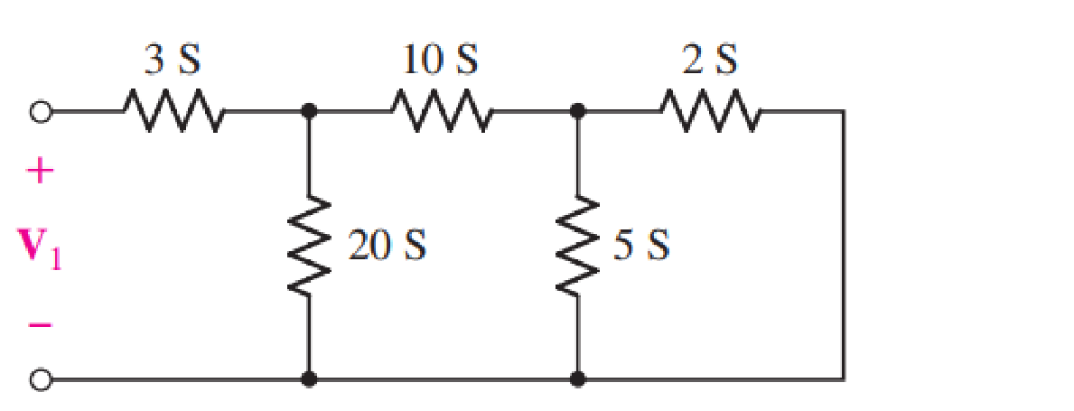
For the one-port network represented schematically in Fig. 16.35, choose the bottom node as the reference; name the junction between the 3, 10, and 20 S conductances V2 and the remaining node V3. (a) Write the three nodal equations. (b) Compute ∆Y. (c) Calculate the input admittance.
Expert Solution & Answer
Want to see the full answer?
Check out a sample textbook solution
Students have asked these similar questions
The Z-parameters
representation of any two-
port network is called
current equations O
voltage equations
Both current and voltage equations O
Non-of-Them
Mutual impedance occur due
.. to the
.
electric field in coils
electric curent in coils
electric voltage in coils
Non-of-Them
Q4. Use a Karnaugh map to minimize the following standard SOP expression: (15 M)
ABC + ABC + ABC + ABC + ABC
Q5. Plot the corresponding SUM and CARRY outputs of half-adder circuit, for the given A and
B inputs. And give the logical expression for both. (15 M)
HA
A
B
Chegg Expert Hiring Signup
X M Chegg Expert Hiring | Complete
O Zoho Creator - Chegg Expert Hir X
india.com/%23Form:Subject test?User_Name=3709413000271934727&Number%3D7
00
Maps
Translate
How do I create a u...
D (5070) Creating and...
B.
How to download, i...
Calculate the z- parameters for the following network:
h,, = 50 2
h12 = 4
h21 =-8
I2
h22 =2 S
Vị
V2
h1 = 82
h12 = 2
h1 = -2
h22 =1S
[57.66 2 3.33 2
(A) z =
3.33 2 0.66 2
39 2
1Ω
(B) z =
6.66 2 3.33
[156 2
127
Chapter 16 Solutions
Loose Leaf for Engineering Circuit Analysis Format: Loose-leaf
Ch. 16.1 - Find the input impedance of the network shown in...Ch. 16.1 - Write a set of nodal equations for the circuit of...Ch. 16.2 - By applying the appropriate 1 V sources and short...Ch. 16.2 - Prob. 4PCh. 16.2 - Prob. 5PCh. 16.3 - Prob. 6PCh. 16.3 - Use Y and Y transformations to determine Rin for...Ch. 16.4 - Find z for the two-port shown in (a) Fig. 16.23a;...Ch. 16.4 - Prob. 9PCh. 16.5 - Prob. 10P
Ch. 16.5 - Prob. 11PCh. 16.6 - Prob. 12PCh. 16 - For the following system of equations, (a) write...Ch. 16 - With regard to the passive network depicted in...Ch. 16 - Determine the input impedance of the network shown...Ch. 16 - For the one-port network represented schematically...Ch. 16 - Prob. 6ECh. 16 - Prob. 7ECh. 16 - Prob. 8ECh. 16 - Prob. 9ECh. 16 - (a) If both the op amps shown in the circuit of...Ch. 16 - Prob. 11ECh. 16 - Prob. 12ECh. 16 - Prob. 13ECh. 16 - Prob. 14ECh. 16 - Prob. 15ECh. 16 - Prob. 16ECh. 16 - Prob. 17ECh. 16 - Prob. 18ECh. 16 - Prob. 19ECh. 16 - Prob. 20ECh. 16 - For the two-port displayed in Fig. 16.49, (a)...Ch. 16 - Prob. 22ECh. 16 - Determine the input impedance Zin of the one-port...Ch. 16 - Determine the input impedance Zin of the one-port...Ch. 16 - Employ Y conversion techniques as appropriate to...Ch. 16 - Prob. 26ECh. 16 - Prob. 27ECh. 16 - Prob. 28ECh. 16 - Compute the three parameter values necessary to...Ch. 16 - It is possible to construct an alternative...Ch. 16 - Prob. 31ECh. 16 - Prob. 32ECh. 16 - Prob. 33ECh. 16 - Prob. 34ECh. 16 - The two-port networks of Fig. 16.50 are connected...Ch. 16 - Prob. 36ECh. 16 - Prob. 37ECh. 16 - Obtain both the impedance and admittance...Ch. 16 - Prob. 39ECh. 16 - Determine the h parameters which describe the...Ch. 16 - Prob. 41ECh. 16 - Prob. 42ECh. 16 - Prob. 43ECh. 16 - Prob. 44ECh. 16 - Prob. 45ECh. 16 - Prob. 46ECh. 16 - Prob. 47ECh. 16 - Prob. 48ECh. 16 - Prob. 49ECh. 16 - Prob. 50ECh. 16 - (a) Employ suitably written mesh equations to...Ch. 16 - Prob. 52ECh. 16 - Prob. 53ECh. 16 - The two-port of Fig. 16.65 can be viewed as three...Ch. 16 - Consider the two separate two-ports of Fig. 16.61....Ch. 16 - Prob. 56ECh. 16 - Prob. 57ECh. 16 - Prob. 58ECh. 16 - (a) Obtain y, z, h, and t parameters for the...Ch. 16 - Four networks, each identical to the one depicted...Ch. 16 - A cascaded 12-element network is formed using four...Ch. 16 - Prob. 62ECh. 16 - Continuing from Exercise 62, the behavior of a ray...
Additional Engineering Textbook Solutions
Find more solutions based on key concepts
Explain the main function of each of the following major components of a PLC: a. Processor module (CPU) b. I/O ...
Programmable Logic Controllers
When travelers from the USA and Canada visit Europe, they encounter a different power distribution system. Wall...
Electric machinery fundamentals
For the “tank” circuit in Fig. 14.79, find the resonant frequency.
Figure 14.79
For Probs. 14.39, 14.71, and 1...
Fundamentals of Electric Circuits
Identify the type of input and output configuration for each diff-amp in Figure 18-35.
Electronics Fundamentals: Circuits, Devices & Applications
A constant voltage of 10V is applied to a 50H inductance, as shown in Figure P3.51 Figure P3 51 The current in ...
Electrical Engineering: Principles & Applications (7th Edition)
Find I0 and I1 in the circuit in Fig.P2.12.
Basic Engineering Circuit Analysis
Knowledge Booster


Learn more about
Need a deep-dive on the concept behind this application? Look no further. Learn more about this topic, electrical-engineering and related others by exploring similar questions and additional content below.Similar questions
- Jl äabiil (CME 446) 1 The Z matrix for the two-port network shown is j20 jo 3+ j2@ Then Z, in the circuit is jo on Za 1 O a. 3+j2w O b. None OC. 3+jw Od. jw O e. j2w f. 3 ENG ) G Aarrow_forwardYl dWl fatoom_basemsh Digital Circuits Lec 6 The institute of Samawa Technical First Year Department Information and Eng. Murtadha kamil Ali Communications Technology Homework: 1) Apply DeMorgan's theorems to each of the following expression A) (A+B+C)D B) ABC+DEF C) AB+CD+EF D) (A+B) +C E) (A+B) +CD F) (A+B)CD+E+F 2) Draw the logic circuit A) Y=(A+B+C)DE Y =ABCDE B) X= ACD+BC 3) The following figure gives the function A) B) LDS 59 ...luln Darrow_forwardPractice: || Find Io in the following circuit using the concept of source transformation, 16.7 Jjarrow_forward
- 4 Find the two-port (pic4) coefficients for A-form equation by voltages and current at open circuit and short circuit regeemes. if r=60 2, x L=20 2, xc =20 2. Check your answer by coefficients ratio.arrow_forwardDetermine the Y-parameters at a frequency of 10 kHz for the two-port network shown in figure below. Present your answer in matrix form. R1 5 Ohm 1 Ohm 400 μF R3 4 Ohm R2 200 μF R5 L5 mom. 5 Ohm 796 µF 6.4 mHarrow_forward3 Find the two-port (pic3) coefficients for A-form equation by voltages and current at open circuit and short circuit regeemes. if øL¡=150 2, wL 2=50 Q, 1/mC =40 Q. Check your answer by coefficients ratio.arrow_forward
- Determine the 3-parameters of the two-port network below. 4 10052 tomm V₁ www 8452 15052 L₂ + V₂ 1arrow_forwardblem #2) Given the network with terminals "t" and "h" across which a load resistor RL will be connected: 48V- 120 Ω 240 Ω 20 Ω voltage, h RL Determine the Thevenin's Equivalent Circuit parameters (VTH and RTH) for the single-port network as "seen" by the load resistor (RL) that will be connected across terminals "t" and "h". Note - in the space provided below, you must show drawings of the circuits that you used in order to solve for each of the Thevenin's parameters. in the following circuit an VTH RTH = V Ωarrow_forwarda) For the two – port networks prove that: Z10 A = Z20 - Z2sarrow_forward
- Q5 Analyze the circuit in Figure Q5: (a) h-parameters for the two-port network. (b) Behavior of dependent source when analyzing hı2 and h22parameters. 14 100 31 200 Figure Q5arrow_forwardSubject: Electrical & Electronics Engineering Course: Power Systems Question: What is a two-port network? Where do you use it and why? Explain.arrow_forward6) A combinational circuit has four inputs (A,B,C,D) and three outputs (X,Y,Z). XYZ represents a binary number whose value equals the number of 1's at the input. For example if ABCD = 1011 then xyz = 011. a. Find the minterm expansions for X,Y and Z. b. Find the maxterm expansions for X,Y and Z.arrow_forward
arrow_back_ios
SEE MORE QUESTIONS
arrow_forward_ios
Recommended textbooks for you
 Introductory Circuit Analysis (13th Edition)Electrical EngineeringISBN:9780133923605Author:Robert L. BoylestadPublisher:PEARSON
 Delmar's Standard Textbook Of ElectricityElectrical EngineeringISBN:9781337900348Author:Stephen L. HermanPublisher:Cengage Learning
 Programmable Logic ControllersElectrical EngineeringISBN:9780073373843Author:Frank D. PetruzellaPublisher:McGraw-Hill Education
 Fundamentals of Electric CircuitsElectrical EngineeringISBN:9780078028229Author:Charles K Alexander, Matthew SadikuPublisher:McGraw-Hill Education
 Electric Circuits. (11th Edition)Electrical EngineeringISBN:9780134746968Author:James W. Nilsson, Susan RiedelPublisher:PEARSON
 Engineering ElectromagneticsElectrical EngineeringISBN:9780078028151Author:Hayt, William H. (william Hart), Jr, BUCK, John A.Publisher:Mcgraw-hill Education,
Introductory Circuit Analysis (13th Edition)
Electrical Engineering
ISBN:9780133923605
Author:Robert L. Boylestad
Publisher:PEARSON
Delmar's Standard Textbook Of Electricity
Electrical Engineering
ISBN:9781337900348
Author:Stephen L. Herman
Publisher:Cengage Learning
Programmable Logic Controllers
Electrical Engineering
ISBN:9780073373843
Author:Frank D. Petruzella
Publisher:McGraw-Hill Education
Fundamentals of Electric Circuits
Electrical Engineering
ISBN:9780078028229
Author:Charles K Alexander, Matthew Sadiku
Publisher:McGraw-Hill Education
Electric Circuits. (11th Edition)
Electrical Engineering
ISBN:9780134746968
Author:James W. Nilsson, Susan Riedel
Publisher:PEARSON
Engineering Electromagnetics
Electrical Engineering
ISBN:9780078028151
Author:Hayt, William H. (william Hart), Jr, BUCK, John A.
Publisher:Mcgraw-hill Education,
Z Parameters - Impedance Parameters; Author: Electrical Engineering Authority;https://www.youtube.com/watch?v=qoD4AoNmySA;License: Standard Youtube License