
Concept explainers
Videos
When travelers from the USA and Canada visit Europe, they encounter a different power distribution system. Wall voltages in North America are 120 V rms at 60 Hz, while typical wall voltages in Europe are 230 V at 50 Hz. Many travelers carry small step-up/step-down transformers so that they can use their appliances in the countries that they are visiting. A typical transformer might be rated at 1 kVA and 115/230 V. It has 500 turns of wire on the 115-V side and 1000 turns of wire on the 230-V side. The magnetization curve for this transformer is shown in Figure P2-2, and can be found in file p22 . mag at this book’s website.
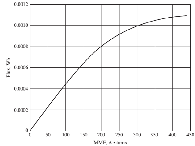
FIGURE P2-2
Magnetization curve for the transformer of Problem 2-5.
- Suppose that this transformer is connected to a 120-V, 60-Hz power source with no load connected to the 240-V side. Sketch the magnetization current that would flow in the transformer. (Use MATLAB to plot the current accurately, if it is available.) What is the rms amplitude of the magnetization current? What percentage of full-load current is the magnetization current?
- Now suppose that this transformer is connected to a 240-V, 50-Hz power source with no load connected to the 120-V side. Sketch the magnetization current that would flow in the transformer. (Use MATLAB to plot the current accurately, if it is available.) What is the rms amplitude of the magnetization current? What percentage of full-load current is the magnetization current?
- In which case is the magnetization current a higher percentage of full-load current? Why?
Want to see the full answer?
Check out a sample textbook solution
Chapter 2 Solutions
Electric machinery fundamentals
Additional Engineering Textbook Solutions
Loose Leaf for Engineering Circuit Analysis Format: Loose-leaf
Microelectronics: Circuit Analysis and Design
Basic Engineering Circuit Analysis
Fundamentals of Applied Electromagnetics (7th Edition)
Fundamentals of Electric Circuits
ANALYSIS+DESIGN OF LINEAR CIRCUITS(LL)


- (a) An ideal single-phase two-winding transformer with turns ratio at=N1/N2 is connected with a series impedance Z2 across winding 2. If one wants to replace Z2, with a series impedance Z1 across winding 1 and keep the terminal behavior of the two circuits to be identical, find Z1 in terms of Z2. (b) Would the above result be true if instead of a series impedance there is a shunt impedance? (c) Can one refer a ladder network on the secondary (2) side to the primary (1) side simply by multiplying every impedance byat2 ?arrow_forwardFor a short-circuit test on a 2-winding transformer, with one winding shorted, can you apply the rated voltage on the other winding? (a) Yes (b) Noarrow_forwardFor an ideal transformer, the efficiency is (a) 0 (b) 100 (c) 50arrow_forward
- Consider an ideal transformer with N1=3000andN2=1000 turns. Let winding 1 be connected to a source whose voltage is e1(t)=100(1| t |)volts for 1t1ande1(t)=0 for | t |1 second. A2- farad capacitor is connected across winding 2. Sketch e1(t),e2(t),i1(t),andi2(t) versus time t.arrow_forwardFor an ideal 2-winding transformer, an impedance Z2 connected across winding 2 (secondary) is referred to winding 1 (primary) by multiplying Z2 by (a) The turns ratio (N1/N2) (b) The square of the turns ratio (N1/N2)2 (c) The cubed turns ratio (N1/N2)3arrow_forwardThe symbol shown is a(n) a. iron core transformer. b. auto transformer. c. current transformer. d. air core transformer.arrow_forward
- A single-phase, 50-kVA,2400/240-V,60-Hz distribution transformer has the following parameters: Resistance of the 2400-V winding: R1=0.75 Resistance of the 240-V winding: R2=0.0075 Leakage reactance of the 2400-V winding: X1=1.0 Leakage reactance of the 240-V winding: X2=0.01 Exciting admittance on the 240-V side =0.003j0.02S (a) Draw the equivalent circuit referred to the high-voltage side of the transformer. (b) Draw the equivalent circuit referred to the low-voltage side of the transformer. Show the numerical values of impedances on the equivalent circuits.arrow_forwardConsider the three single-phase two-winding transformers shown in Figure 3.37. The high-voltage windings are connected in Y. (a) For the low-voltage side, connect the windings in , place the polarity marks, and label the terminals a, b, and c in accordance with the American standard. (b) Relabel the terminals a, b, and c such that VAN is 90 out of phase with Va for positive sequence.arrow_forwardThe ratings of a three-phase three-winding transformer are Primary(1): Y connected 66kV,15MVA Secondary (2): Y connected, 13.2kV,10MVA Tertiary (3): A connected, 2.3kV,5MVA Neglecting winding resistances and exciting current, the per-unit leakage reactances are X12=0.08 on a 15-MVA,66-kV base X13=0.10 on a 15-MVA,66-kV base X23=0.09 on a 10-MVA,13.2-kV base (a) Determine the per-unit reactances X1,X2,X3 of the equivalent circuit on a 15-MVA,66-kV base at the primary terminals. (b) Purely resistive loads of 7.5 MW at 13.2 kV and 5 MW at 2.3kV are connected to the secondary and tertiary sides of the transformer, respectively. Draw the per- unit impedance diagram, showing the per-unit impedances on a 15-MVA,66-kV base at the primary terminals.arrow_forward
- A single-phase step-down transformer is rated 13MVA,66kV/11.5kV. With the 11.5 kV winding short-circuited, rated current flows when the voltage applied to the primary is 5.5 kV. The power input is read as 100 kW. Determine Req1andXeq1 in ohms referred to the high-voltage winding.arrow_forwardA 23/230-kV step-up transformer feeds a three-phase transmission line, which in turn supplies a 150-MVA,0.8 lagging power factor load through a step-down 230/23-kV transformer. The impedance of the line and transformers at 230kVis18+j60. Determine the tap setting for each transformer to maintain the voltage at the load at 23 kV.arrow_forwardA 4 kVA, 400/200 V single-phase transformer has resistance of 0.02 p.u. and reactance of 0.06 p.u. Its actual resistance and reactance refferd to h.v. side are ?arrow_forward
 Power System Analysis and Design (MindTap Course ...Electrical EngineeringISBN:9781305632134Author:J. Duncan Glover, Thomas Overbye, Mulukutla S. SarmaPublisher:Cengage Learning
 Electricity for Refrigeration, Heating, and Air C...Mechanical EngineeringISBN:9781337399128Author:Russell E. SmithPublisher:Cengage Learning
 Delmar's Standard Textbook Of ElectricityElectrical EngineeringISBN:9781337900348Author:Stephen L. HermanPublisher:Cengage Learning