
Fundamentals of Electric Circuits
6th Edition
ISBN: 9780078028229
Author: Charles K Alexander, Matthew Sadiku
Publisher: McGraw-Hill Education
expand_more
expand_more
format_list_bulleted
Videos
Textbook Question
Chapter 19.4, Problem 6PP
Find the impedance at the input port of the circuit in Fig. 19.27.
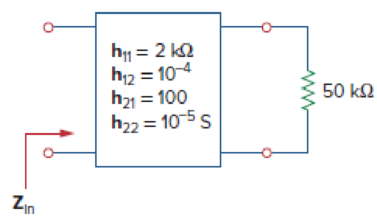
Figure 19.27
Expert Solution & Answer
Want to see the full answer?
Check out a sample textbook solution
Students have asked these similar questions
Find the h parameters of the rwo-porn in Fig. 19.44.
Example 19.13
J45
25
45
ヨー25
-J6 S
-ww-
-ww-
Practice Problem 19.6
Find the impedance at the input port of the circuit in Fig. 19.27.
Answer: 1.6667 kN.
h1 = 2 k2
h12 = 104
h21 = 100
h2 = 10-5 s
50 k2
%3D
Zin
Figure 19.27
For Practice Prob. 19.6.
Practice Problem 19.6
Find the impedance at the input port of the cicuit in Fig. 19.27.
Answer: 1.6667 kfl.
b =2 ka
= 10
b = 100
= 10s
30 ka
Figure 19.27
For Practice Prob. 19.6.
Chapter 19 Solutions
Fundamentals of Electric Circuits
Ch. 19.2 - Find the z parameters of the two-port network in...Ch. 19.2 - Calculate I1 and I2 in the two-port of Fig. 19.11....Ch. 19.3 - Obtain the y parameters for the T network shown in...Ch. 19.3 - Obtain the y parameters for the circuit in Fig....Ch. 19.4 - Determine the h parameters for the circuit in Fig....Ch. 19.4 - Find the impedance at the input port of the...Ch. 19.4 - For the ladder network in Fig. 19.30, determine...Ch. 19.5 - Find the transmission parameters for the circuit...Ch. 19.5 - Prob. 9PPCh. 19.6 - Determine [y] and [T] of a two-port network whose...
Ch. 19.6 - Find the z parameters of the op amp circuit in...Ch. 19.7 - Find V2/Vs in the circuit in Fig. 19.43. Figure...Ch. 19.7 - Obtain the y parameters for the network in Fig....Ch. 19.7 - Obtain the ABCD parameter representation of the...Ch. 19.8 - Obtain the h parameters for the network in Fig....Ch. 19.8 - Obtain the z parameters of the circuit in Fig....Ch. 19.9 - For the transistor amplifier of Fig. 19.60, find...Ch. 19.9 - Prob. 18PPCh. 19 - For the single-element two-port network in Fig....Ch. 19 - For the single-element two-port network in Fig....Ch. 19 - For the single-element two-port network in Fig....Ch. 19 - For the single-element two-port network in Fig....Ch. 19 - For the single-element two-port network in Fig....Ch. 19 - For the single-element two-port network in Fig....Ch. 19 - When port 1 of a two-port circuit is...Ch. 19 - A two-port is described by the following...Ch. 19 - If a two-port is reciprocal, which of the...Ch. 19 - Prob. 10RQCh. 19 - Obtain the z parameters for the network in Fig....Ch. 19 - Find the impedance parameter equivalent of the...Ch. 19 - Find the z parameters of the circuit in Fig....Ch. 19 - Using Fig. 19.68, design a problem to help other...Ch. 19 - Obtain the z parameters for the network in Fig....Ch. 19 - Compute the z parameters of the circuit in Fig....Ch. 19 - Calculate the z parameters of the circuit in Fig....Ch. 19 - Find the z parameters of the two-port in Fig....Ch. 19 - The y parameters of a network are:...Ch. 19 - Construct a two-port that realizes each of the...Ch. 19 - Determine a two-port network that is represeted by...Ch. 19 - For the circuit shown in Fig. 19.73, let z=106412...Ch. 19 - Determine the average power delivered to ZL = 5 +...Ch. 19 - For the two-port network shown in Fig. 19.75, show...Ch. 19 - For the two-port circuit in Fig. 19.76,...Ch. 19 - For the circuit in Fig. 19.77, at = 2 rad/s, z11...Ch. 19 - Prob. 17PCh. 19 - Calculate the y parameters for the two-port in...Ch. 19 - Using Fig. 19.80, design a problem to help other...Ch. 19 - Find the y parameters for the circuit in Fig....Ch. 19 - Obtain the admittance parameter equivalent circuit...Ch. 19 - Obtain the y parameters of the two-port network in...Ch. 19 - (a) Find the y parameters of the two-port in Fig....Ch. 19 - Find the resistive circuit that represents these y...Ch. 19 - Prob. 25PCh. 19 - Calculate [y] for tle two-port in Fig. 19.85.Ch. 19 - Find the y parameters for the Circuit in Fig....Ch. 19 - In the circuit of Fig. 19.65, the input port is...Ch. 19 - In the bridge circuit of Fig. 19.87, I1 = 20 A and...Ch. 19 - Find the h parameters for the networks in Fig....Ch. 19 - Determine the hybrid parameters for the network in...Ch. 19 - Using Fig. 19.90, design a problem to help other...Ch. 19 - Obtain the h parameters for the two-port of Fig....Ch. 19 - Obtain the h and g parameters of the two-port in...Ch. 19 - Determine the h parameters for the network in Fig....Ch. 19 - For the two-port in Fig. 19.94. h=16320.01S Find:...Ch. 19 - The input port of the circuit in Fig. 19.79 is...Ch. 19 - The h parameters of the two-port of Fig. 19.95...Ch. 19 - Obtain the g parameters for the wye circuit of...Ch. 19 - Using Fig. 19.97, design a problem to help other...Ch. 19 - For the two-port in Fig. 19.75, show that...Ch. 19 - The h parameters of a two-port device are given by...Ch. 19 - Find the transmission parameters for the...Ch. 19 - Using Fig. 19.99, design a problem to help other...Ch. 19 - Find the ABCD parameters for the circuit in Fig....Ch. 19 - Find the transmission parameters for the circuit...Ch. 19 - Obtain the ABCD parameters for the network in Fig....Ch. 19 - For a two-port, let A = 4, B = 30 , C = 0.1 S, and...Ch. 19 - Using impedances in the s-domain, obtain the...Ch. 19 - Derive the s-domain expression for the t...Ch. 19 - Obtain the t parameters for the network in Fig....Ch. 19 - (a) For the T network in Fig. 19.106, show that...Ch. 19 - Prob. 53PCh. 19 - Show that the transmission parameters of a...Ch. 19 - Prove that the g parameters can be obtained from z...Ch. 19 - For the network of Fig. 19.107, obtain VoVs....Ch. 19 - Given the transmission parameters T=32017 obtain...Ch. 19 - Design a problem to help other students better...Ch. 19 - Given that g=0.06S0.40.22 determine: (a) [z] (b)...Ch. 19 - Design a T network necessary to realize the...Ch. 19 - For the bridge circuit in Fig. 19.108, obtain: (a)...Ch. 19 - Find the z parameters of the op amp circuit in...Ch. 19 - Determine the z parameters of the two-port in Fig....Ch. 19 - Determine the y parameters at = 1,000 rad/s for...Ch. 19 - What is the y parameter presentation of the...Ch. 19 - In the two-port of Fig. 19.113, let y12 = y21 = 0,...Ch. 19 - If three copies of the circuit in Fig. 19.114 are...Ch. 19 - Obtain the h parameters for the network in Fig....Ch. 19 - The circuit in Fig. 19.116 may be regarded as two...Ch. 19 - For the parallel-series connection of the two...Ch. 19 - Determine the z parameters for the network in Fig....Ch. 19 - A series-parallel connection of two two-ports is...Ch. 19 - Three copies of the circuit shown in Fig. 19.70...Ch. 19 - Determine the ABCD parameters of the circuit in...Ch. 19 - For the individual two-ports shown in Fig. 19.121...Ch. 19 - Use PSpice or MultiSim to obtain the z parameters...Ch. 19 - Using PSpice or MultiSim, find the h parameters of...Ch. 19 - Obtain the h parameters at = 4 rad/s for the...Ch. 19 - Use PSpice or MultiSim to determine the z...Ch. 19 - Use PSpice or MultiSim to find the z parameters of...Ch. 19 - Repeat Prob. 19.26 using PSpice or MultiSim....Ch. 19 - Use PSpice or MultiSim to rework Prob. 19.31....Ch. 19 - Rework Prob. 19.47 using PSpice or MultiSim....Ch. 19 - Using PSpice or MultiSim, find the transmission...Ch. 19 - At =1rad/s, find the transmission parameters of...Ch. 19 - Obtain the g parameters for the network in Fig....Ch. 19 - For the circuit shown in Fig. 19.129, use PSpice...Ch. 19 - Using the y parameters, derive formulas for Zin,...Ch. 19 - A transistor has the following parameters in a...Ch. 19 - A transistor with hfe=120,hie=2khre=104,hoe=20S is...Ch. 19 - For the transistor network of Fig. 19.130,...Ch. 19 - Prob. 92PCh. 19 - Prob. 93PCh. 19 - A transistor in its common-emitter mode is...Ch. 19 - Prob. 95PCh. 19 - Prob. 96PCh. 19 - Synthesize the transfer function...Ch. 19 - A two-stage amplifier in Fig. 19.134 contains two...Ch. 19 - Assume that the two circuits in Fig. 19.135 are...
Additional Engineering Textbook Solutions
Find more solutions based on key concepts
With respect to the circuit in Fig. 5.90, (a) employ Thévenin’s theorem to determine the equivalent network see...
Loose Leaf for Engineering Circuit Analysis Format: Loose-leaf
The current source in the circuit shown generates the current pulse
Find (a) v (0); (b) the instant of time gr...
Electric Circuits. (11th Edition)
Identify the type of input and output configuration for each diff-amp in Figure 18-35.
Electronics Fundamentals: Circuits, Devices & Applications
Explain the main function of each of the following major components of a PLC: a. Processor module (CPU) b. I/O ...
Programmable Logic Controllers
A constant voltage of 10V is applied to a 50H inductance, as shown in Figure P3.51 Figure P3 51 The current in ...
Electrical Engineering: Principles & Applications (7th Edition)
The voltage source of the circuit shown in Fig. P1.29 is given by s(t)=25cos(4104t45)(V). Obtain an expression ...
Fundamentals of Applied Electromagnetics (7th Edition)
Knowledge Booster


Learn more about
Need a deep-dive on the concept behind this application? Look no further. Learn more about this topic, electrical-engineering and related others by exploring similar questions and additional content below.Similar questions
- Find the à parameters of the nerwork in Fig. 19.49. Example 19.15 Solution: From Eq (19.16), 612 ww 10 2 10 2 showing that h,, and h, can be found by setting V, = 0. Also by setting I = 1 A, h becomes V/1 while h2: becomes I2/1. With this in mind we draw the schematic in Fig. 19.50(a). We insert a 1-A dc current source Figure 19.49 For Example 19.15.arrow_forwardObtain the z parameters for the network in Fig. 19.69 as functions of s. IH 王 wwarrow_forwardChapter 19, Problem 4. Caiculate the : parameters for the circuit in Fig. 19.68. Figure 19.68arrow_forward
- Solve the question in the simplest way Determine the y parameters for the two-port shown in Fig. 19.17. JAS! dustig! 21 892 www 452 www ww 252arrow_forwardPractice Problem 19.6 Find the impedance at the imput port of the circuit in Fig. 19.27. =2 k Answer: 1.6667 kl. = 100 b= 10s 50 ka Figure 19.27 For Practice Prob. 19.6. rircut in F: 19.28arrow_forwardFind the z parameters of the circuit in Fig. 19.67. -/10 2 ww Figure 19.67arrow_forward
- Determine the y parameters for the two-port shown in Fig. 19.17. Example 19.4 21 Solution: We follow the same procedure as in the previous example. To get y and y21, we use the circuit in Fig. 19.18(a), in which port 2 is short- circuited and a current source is applied to port 1. At node 1, -ww- ww V - V. V.-0 2 V. = 21, + 20 4. V, - V, But I, = therefore, Figure 19.17 For Example 19 4arrow_forwardFind the y-parameters of the 2-port in the figure. R 1 2arrow_forwardPractice Problem 19.6 h = 2 kΩ h12 = 104 h₂1 = 100 h22 = 10-5 S Zin Figure 19.27 For Practice Prob. 19.6. www 50 ΚΩ Find the impedance at the input port of the circuit in Fig. 19.27. Answer: 1.6667 kN.arrow_forward
- Derive the expressions for the g parameters as functions of the zparameters.arrow_forwardFind the y-parameters for the 2-port shown below. bV2 R :C V2 V1 aiarrow_forwardCalculate I, and I2 in the two-port of Fig. 19.11. I 2Ω Z11 = 6 Q Z12 = -j4 Q Z21 = -j4 Q Z22 = 8 Q + 2/30° V (± V2 Figure 19.11 For Practice Prob. 19.2. Answer: 200/30° mA, 100/120° mA.arrow_forward
arrow_back_ios
SEE MORE QUESTIONS
arrow_forward_ios
Recommended textbooks for you
 Introductory Circuit Analysis (13th Edition)Electrical EngineeringISBN:9780133923605Author:Robert L. BoylestadPublisher:PEARSON
 Delmar's Standard Textbook Of ElectricityElectrical EngineeringISBN:9781337900348Author:Stephen L. HermanPublisher:Cengage Learning
 Programmable Logic ControllersElectrical EngineeringISBN:9780073373843Author:Frank D. PetruzellaPublisher:McGraw-Hill Education
 Fundamentals of Electric CircuitsElectrical EngineeringISBN:9780078028229Author:Charles K Alexander, Matthew SadikuPublisher:McGraw-Hill Education
 Electric Circuits. (11th Edition)Electrical EngineeringISBN:9780134746968Author:James W. Nilsson, Susan RiedelPublisher:PEARSON
 Engineering ElectromagneticsElectrical EngineeringISBN:9780078028151Author:Hayt, William H. (william Hart), Jr, BUCK, John A.Publisher:Mcgraw-hill Education,
Introductory Circuit Analysis (13th Edition)
Electrical Engineering
ISBN:9780133923605
Author:Robert L. Boylestad
Publisher:PEARSON
Delmar's Standard Textbook Of Electricity
Electrical Engineering
ISBN:9781337900348
Author:Stephen L. Herman
Publisher:Cengage Learning
Programmable Logic Controllers
Electrical Engineering
ISBN:9780073373843
Author:Frank D. Petruzella
Publisher:McGraw-Hill Education
Fundamentals of Electric Circuits
Electrical Engineering
ISBN:9780078028229
Author:Charles K Alexander, Matthew Sadiku
Publisher:McGraw-Hill Education
Electric Circuits. (11th Edition)
Electrical Engineering
ISBN:9780134746968
Author:James W. Nilsson, Susan Riedel
Publisher:PEARSON
Engineering Electromagnetics
Electrical Engineering
ISBN:9780078028151
Author:Hayt, William H. (william Hart), Jr, BUCK, John A.
Publisher:Mcgraw-hill Education,
Introduction to Two-Port Networks; Author: ALL ABOUT ELECTRONICS;https://www.youtube.com/watch?v=ru2ItcD6unI;License: Standard Youtube License