
Videos
(a)
Find the current through the emf device and each resistor in circuit 1.
(a)
Answer to Problem 39PQ
The current through the Emf device and each resistor in circuit 1 is
Explanation of Solution
According to Kirchhoff’s junction rule, in any junction, the sum of the all the currents entering the junction equals the sum of all the currents exiting the junction.
Redraw the circuit 1 and labeled it as given below

In parallel circuit, voltage across all three resistors is same that means potential difference between node A and node B is same (
According to Ohm’s law,
Here,
Rearrange the equation (I) in terms of total current
Write the expression for equivalent resistance as.
Rearrange the above expression.
Write the expression for current
Here,
Write the expression for current
Here,
Write the expression for current
Here,
Conclusion:
Substitute
Substitute
Substitute
Thus, the current in circuit 1 is
Substitute
Substitute
Substitute
Thus, the current through the Emf device and each resistor in circuit 1 is
(b)
Find the current through the emf device and each resistor in circuit 2 refer to figure P29.28.
(b)
Answer to Problem 39PQ
The current through the Emf device and each resistor in circuit 2 is
Explanation of Solution
According to Kirchhoff’s junction rule, in any junction, the sum of the all the currents entering the junction equals the sum of all the currents exiting the junction.
Redraw the circuit 2 and labeled it as given below.
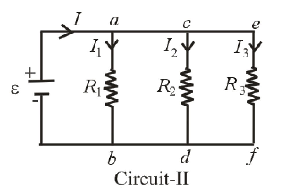
In parallel circuit 2, voltage across all three resistors is same that means potential difference between node a and node b, node c & node d and node e & node f are same
Write the expression for current
Here,
Write the expression for current
Here,
Write the expression for current
Here,
Conclusion:
Substitute
Substitute
Substitute
Thus, the current in circuit 1 is
Substitute
Substitute
Substitute
Thus, the current for the given circuit resistance is
Want to see more full solutions like this?
Chapter 29 Solutions
Physics for Scientists and Engineers: Foundations and Connections


- Three resistors with resistances R1 = R/2 and R2 = R3 = R are connected as shown, and a potential difference of 225 V is applied across terminals a and b (Fig. P29.49). a. If the resistor R1 dissipates 75.0 W of power, what is the value of R? b. What is the total power supplied to the circuit by the emf? c. What is the potential difference across each of the three resistors?arrow_forwardTwo circuits made up of identical ideal emf devices ( = 1.67 V) and resistors (R = 35.9 ) are shown in Figure P29.8. What is the potential difference Vb Va a. for circuit 1 and b. for circuit 2? What is the current in the resistor c. in circuit 1 and d. in circuit 2?arrow_forwardEight real batteries, each with an emf of 5.00 V and an internal resistance of 0.200 , are connected end to end in a loop as in Figure P29.13. What is the terminal voltage across one of the batteries between points a and b?arrow_forward
- In Figure P29.81, N real batteries, each with an emf and internal resistance r, are connected in a closed ring. A resistor R can be connected across any two points of this ring, causing there to be n real batteries in one branch and N n resistors in the other branch. Find an expression for the current through the resistor R in this case.arrow_forwardEach resistor shown in Figure P29.36 has a resistance of 100.0 . An ideal emf device (120.0 V) is connected to points a and b via two leads (not shown in the figure). Find the current that flows through the emf device.arrow_forward(a) What is the average power output of a heart defibrillator that dissipates 400 J of energy in 10.0 ms? (b) Considering the high-power output, why doesn’t the defibrillator produce serious bums?arrow_forward
- The circuit shown in Figure P28.78 is set up in the laboratory to measure an unknown capacitance C in series with a resistance R = 10.0 M powered by a battery whose emf is 6.19 V. The data given in the table are the measured voltages across the capacitor as a function of lime, where t = 0 represents the instant at which the switch is thrown to position b. (a) Construct a graph of In (/v) versus I and perform a linear least-squares fit to the data, (b) From the slope of your graph, obtain a value for the time constant of the circuit and a value for the capacitance. v(V) t(s) In (/v) 6.19 0 5.56 4.87 4.93 11.1 4.34 19.4 3.72 30.8 3.09 46.6 2.47 67.3 1.83 102.2arrow_forwardA Each resistor shown in Figure P29.36 has resistance R. An ideal emf device () is connected to points a and b via two leads (not shown in the figure). Find an expression for the current through the emf device. FIGURE P29.36arrow_forwardFigure P29.41 shows three resistors (R1 = 14.0 , R2 = 8.00 , and R3 = 10.0 ) and two batteries connected in a circuit. a. What is the current in each of the resistors? b. How much power is delivered to each of the resistors?arrow_forward
- Problem 3: Consider a circuit shown in the figure. Ignore the internal resistances of the batteries. ℰ1 = 34 Vℰ2 = 46 VR1 = 10 ΩR2 = 4 ΩR3 = 8 Ω. 1. Write the equation of potential change in loop DCAF in terms of the circuit elements. 2. Solve the three equations to get I3. 3. Calculate the numerical value of I3 in A. 4. Calculate the numerical value of I2 in A. 5. Calculate the numerical value of I1 in A.arrow_forwardB. The circuit at right has three resistors, R1, R2 and R2 connected with two ideal batteries. The three R1 20 Q currents in each leg of the circuit are labeled as ią, ib, and i, as shown. la ic R2 i. Apply Kirchhoff's laws to the circuit and write the three equations that represent the circuit below. 40 Q R3 80 Q + BAT1 9 V ВАТ2 12 V ii. Solve the system of equations to find as ia, ib, and ic. Show your work.arrow_forwarda. What are the magnitude and direction of the current in the 18 Ω resistor in Figure P23.7?b. Draw a graph of the potential as a function of the distance traveled through the circuit, traveling clockwise from V = 0 V at the lower left corner. See Figure P23.9 for an example of such a graph.arrow_forward
 Physics for Scientists and Engineers: Foundations...PhysicsISBN:9781133939146Author:Katz, Debora M.Publisher:Cengage Learning
 Physics for Scientists and Engineers with Modern ...PhysicsISBN:9781337553292Author:Raymond A. Serway, John W. JewettPublisher:Cengage Learning
 Principles of Physics: A Calculus-Based TextPhysicsISBN:9781133104261Author:Raymond A. Serway, John W. JewettPublisher:Cengage Learning
 Physics for Scientists and Engineers, Technology ...PhysicsISBN:9781305116399Author:Raymond A. Serway, John W. JewettPublisher:Cengage Learning