
Videos
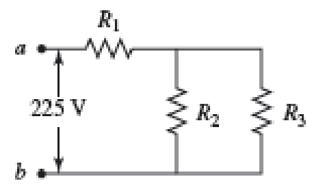
Three resistors with resistances R1 = R/2 and R2 = R3 = R are connected as shown, and a potential difference of 225 V is applied across terminals a and b (Fig. P29.49).
a. If the resistor R1 dissipates 75.0 W of power, what is the value of R?
b. What is the total power supplied to the circuit by the emf?
c. What is the potential difference across each of the three resistors?
(a)
Find the value of resistance from the given circuit.
Answer to Problem 49PQ
The value of
Explanation of Solution
Refer the figure
Write the equivalent resistance of the parallel circuit as.
Here
Since
Write the equivalent resistance of circuit as.
Here,
Write the expression for the current drawn by the circuit from the voltage applied as.
Here
Write the expression for power dissipated across
Here,
Conclusion:
Substitute
Rearrange the terms in above equation
Substitute
Substitute
Substitute
Rearrange the terms in above equation
Thus, the value of
(b)
Find the total power supplied to the circuit.
Answer to Problem 49PQ
The total power supplied to the circuit is
Explanation of Solution
The total power supplied to the circuit is given as
Here
Conclusion:
Substitute
Substitute
Thus, the total power supplied to the circuit is
(c)
Find the potential difference across the three resistors.
Answer to Problem 49PQ
The potential difference across the resistance
Explanation of Solution
Write the expression for the potential difference across the resistance
Here
Write the expression for the remaining potential drop is across the parallel combination of
Here
Conclusion:
Substitute
Substitute
Thus, the potential difference across the resistance
Want to see more full solutions like this?
Chapter 29 Solutions
Physics for Scientists and Engineers: Foundations and Connections


- (a) What is the average power output of a heart defibrillator that dissipates 400 J of energy in 10.0 ms? (b) Considering the high-power output, why doesn’t the defibrillator produce serious bums?arrow_forward(a) Determine the equilibrium charge on the capacitor in the circuit of Figure P27.46 as a function of R. (b) Evaluate the charge when R = 10.0 . (c) Can the charge on the capacitor be zero? If so, for what value of R? (d) What is the maximum possible magnitude of the charge on the capacitor? For what value of R is it achieved? (c) Is it experimentally meaningful to take R = ? Explain your answer. If so, what charge magnitude does it imply? Figure P27.46arrow_forwardFigure P29.41 shows three resistors (R1 = 14.0 , R2 = 8.00 , and R3 = 10.0 ) and two batteries connected in a circuit. a. What is the current in each of the resistors? b. How much power is delivered to each of the resistors?arrow_forward
- Figure P29.42 shows five resistors and two batteries connected in a circuit. What are the currents I1, I2, and I3? FIGURE P29.42arrow_forwardEach resistor shown in Figure P29.36 has a resistance of 100.0 . An ideal emf device (120.0 V) is connected to points a and b via two leads (not shown in the figure). Find the current that flows through the emf device.arrow_forwardThe circuit shown in Figure P28.78 is set up in the laboratory to measure an unknown capacitance C in series with a resistance R = 10.0 M powered by a battery whose emf is 6.19 V. The data given in the table are the measured voltages across the capacitor as a function of lime, where t = 0 represents the instant at which the switch is thrown to position b. (a) Construct a graph of In (/v) versus I and perform a linear least-squares fit to the data, (b) From the slope of your graph, obtain a value for the time constant of the circuit and a value for the capacitance. v(V) t(s) In (/v) 6.19 0 5.56 4.87 4.93 11.1 4.34 19.4 3.72 30.8 3.09 46.6 2.47 67.3 1.83 102.2arrow_forward
- Figure P29.77 shows a circuit with two batteries and three resistors. a. How much current flows through the 2.00- resistor? b. What is the potential difference between points a and b in the circuit?arrow_forwardAn ideal emf device (24.0 V) is connected to a set of resistors as shown in Figure P29.66. If R1 = 22.5 , R2 = 52.5 , R3 = 125 , and R4 = 75.0 , what is the voltage drop across each resistor?arrow_forwardEight real batteries, each with an emf of 5.00 V and an internal resistance of 0.200 , are connected end to end in a loop as in Figure P29.13. What is the terminal voltage across one of the batteries between points a and b?arrow_forward
- In Figure P29.81, N real batteries, each with an emf and internal resistance r, are connected in a closed ring. A resistor R can be connected across any two points of this ring, causing there to be n real batteries in one branch and N n resistors in the other branch. Find an expression for the current through the resistor R in this case.arrow_forwardA 5.0 F capacitor is charged to 12 V and placed in the RC circuit shown. At time t = 0 s, the switch is closed, allowing the capacitor to discharge into the 400 Q resistor. a. What is the time constant (in seconds) for this RC circuit? b. After how many time constants is the charge on the capacitor one-fourth of its initial value?arrow_forwardChapter 32, Problem 018 Your answer is partially correct. Try again. The circuit in the figure consists of switch S, a 4.50 V ideal battery, a 35.0 M2 resistor, and an airfilled capacitor. The capacitor has parallel circular plates of radius 5.10 cm, separated by 1.50 mm. At time t = 0, switch S is closed to begin charging the capacitor. The electric field between the plates is uniform. At t = 160 µs, what is the magnitude of the magnetic field within the capacitor, at radial distance 3.30 cm? C S R Number Units T. Use correct number of significant digits; the tolerance is +/-1 in the 3rd significant digitarrow_forward
 Physics for Scientists and Engineers: Foundations...PhysicsISBN:9781133939146Author:Katz, Debora M.Publisher:Cengage Learning
 Physics for Scientists and Engineers, Technology ...PhysicsISBN:9781305116399Author:Raymond A. Serway, John W. JewettPublisher:Cengage Learning
 Physics for Scientists and EngineersPhysicsISBN:9781337553278Author:Raymond A. Serway, John W. JewettPublisher:Cengage Learning
 Physics for Scientists and Engineers with Modern ...PhysicsISBN:9781337553292Author:Raymond A. Serway, John W. JewettPublisher:Cengage Learning