
Vector Mechanics for Engineers: Statics and Dynamics
12th Edition
ISBN: 9781259638091
Author: Ferdinand P. Beer, E. Russell Johnston Jr., David Mazurek, Phillip J. Cornwell, Brian Self
Publisher: McGraw-Hill Education
expand_more
expand_more
format_list_bulleted
Videos
Textbook Question
Chapter 3.3, Problem 3.87P
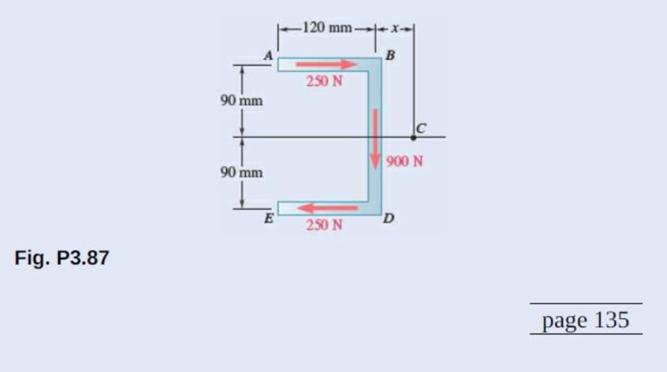
The shearing forces exerted on the cross section of a steel channel can be represented by a 900-N vertical force and two 250-N horizontal forces as shown. Replace this force and couple with a single force F applied at point C, and determine the distance x from C to line BD. (Point C is defined as the shear center of the section.)
Expert Solution & Answer
Want to see the full answer?
Check out a sample textbook solution
Students have asked these similar questions
Reduce the given loading system to a force-couple system at point A. Then determine the distance x to the right of point A at which the
resultant of the three forces acts.
380 lb
9"
15"
HJ
12"
640 lb
A
Answers:
Force-couple system at A. The force is positive if up, and the moment is positive if counterclockwise.
R=
M=
i
X=
i
Resultant
330 lb
i
lb
lb-in.
in.
Q1) The flanged steel cantilever beam with riveted braket is subjected to
the couple and two forces shown, and their effect on the design of
attachment at A must be determined. Replace the two forces and
couple by an equivalent couple by an equivalent couple M and
resultant force R at A. Find the magnitude of the R and the angle 0x
which R makes with the positive x-axis
2200 N
0.5 m
1.5 m
60°
0.15 m
|A
0.15 m
600 N.m
L--x
4
1100 N
The man exerts a force P of magnitude 250 N on the handles of the
wheel barrow. Knowing that the resultant of the forces P, Q (the
reaction at the wheel), and W (the weight of the wheelbarrow) is the
force R 50 i N, determine W
30
W
4. A machine component is subjected to the forces and couples as shown. If P = 60 N,
determine the magnitude and direction of the resultant force as well as the location
where the resultant force passes through vertical line GF and horizontal line GH.
15
200 N
50 mm
520 mm
E
50 mm
240 mm
42 N-m
D
120 N
70⁰
40 N-m
640 mm
H
80 N
180 mm
B
+50mm
Ans:
(a) 0.365 m above G
(b) 0.227 m to the right of G
Chapter 3 Solutions
Vector Mechanics for Engineers: Statics and Dynamics
Ch. 3.1 - A foot valve for a pneumatic system is hinged at...Ch. 3.1 - 3.2A foot valve for a pneumatic system is hinged...Ch. 3.1 - It is known that a vertical force of 200 lb is...Ch. 3.1 - A 300-N force is applied at A as shown. Determine...Ch. 3.1 - A 300-N force is applied at A as shown. Determine...Ch. 3.1 - An 8-lb force P is applied to a shift lever....Ch. 3.1 - For the shift lever shown, determine the magnitude...Ch. 3.1 - An 11-lb force P is applied to a shift lever. The...Ch. 3.1 - Rod AB is held in place by the cord AC. Knowing...Ch. 3.1 - Rod AB is held in place by the cord AC. Knowing...
Ch. 3.1 - 3.11 and 3.12The tailgate of a car is supported by...Ch. 3.1 - 3.11 and 3.12The tailgate of a car is supported by...Ch. 3.1 - 3.13 and 3.14It is known that the connecting rod...Ch. 3.1 - 3.13 and 3.14It is known that the connecting rod...Ch. 3.1 - Form the vector product P1 P2 and use the result...Ch. 3.1 - The vectors P and Q are two adjacent sides of a...Ch. 3.1 - A plane contains the vectors A and B. Determine...Ch. 3.1 - A line passes through the points (4 m, 3 m) and (2...Ch. 3.1 - Prob. 3.19PCh. 3.1 - Determine the moment about the origin O of the...Ch. 3.1 - Before the trunk of a large tree is felled, cables...Ch. 3.1 - The 12-ft boom AB has a fixed end A. A steel cable...Ch. 3.1 - A 200-N force is applied as shown to the bracket...Ch. 3.1 - A force P of magnitude 200 N acts along the...Ch. 3.1 - A 6-ft-long fishing rod AB is securely anchored in...Ch. 3.1 - A precast concrete wall section is temporarily...Ch. 3.1 - In Prob. 3.22, determine the perpendicular...Ch. 3.1 - In Prob. 3.23, determine the perpendicular...Ch. 3.1 - In Prob. 3.24, determine the perpendicular...Ch. 3.1 - In Prob. 3.25, determine the perpendicular...Ch. 3.1 - In Prob. 3.25, determine the perpendicular...Ch. 3.1 - In Prob. 3.26, determine the perpendicular...Ch. 3.1 - In Prob. 3.26, determine the perpendicular...Ch. 3.1 - Determine the value of a that minimizes the...Ch. 3.2 - Given the vectors P = 2i + j + 2k, Q = 3i + 4j ...Ch. 3.2 - Form the scalar product B C and use the result...Ch. 3.2 - Three cables are attached to the top of the tower...Ch. 3.2 - Three cables are attached to the top of the tower...Ch. 3.2 - Knowing that the tension in cable AC is 280 lb,...Ch. 3.2 - Prob. 3.40PCh. 3.2 - Ropes AB and BC are two of the ropes used to...Ch. 3.2 - Prob. 3.42PCh. 3.2 - The 20-in. tube AB can slide along a horizontal...Ch. 3.2 - Solve Prob. 3.43 for the position corresponding to...Ch. 3.2 - Determine the volume of the parallelepiped of Fig....Ch. 3.2 - Given the vectors P = 3i + 2j + k, Q = 5i + j 2k,...Ch. 3.2 - A crane is oriented so that the end of the 25-m...Ch. 3.2 - 3.48The 25-m crane boom AO lies in the yz plane....Ch. 3.2 - To loosen a frozen valve, a force F with a...Ch. 3.2 - 3.50When a force F is applied to the handle of the...Ch. 3.2 - The 0.61 1.00-m lid ABCD of a storage bin is...Ch. 3.2 - 3.52The 0.61 1.00-m lid ABCD of a storage bin is...Ch. 3.2 - A farmer uses cables and winch pullers B and E to...Ch. 3.2 - Solve Prob. 3.53 when the tension in cable AB is...Ch. 3.2 - A force P of magnitude 520 lb acts on the frame...Ch. 3.2 - 3.56A force P acts on the frame shown at point E....Ch. 3.2 - The frame ACD is hinged at A and D and is...Ch. 3.2 - In Prob. 3.57, determine the moment about the...Ch. 3.2 - The triangular plate ABC is supported by...Ch. 3.2 - 3.60The triangular plate ABC is supported by...Ch. 3.2 - A regular tetrahedron has six edges of length a. A...Ch. 3.2 - Prob. 3.62PCh. 3.2 - Prob. 3.63PCh. 3.2 - In Prob. 3.55, determine the perpendicular...Ch. 3.2 - In Prob. 3.56, determine the perpendicular...Ch. 3.2 - In Prob. 3.57, determine the perpendicular...Ch. 3.2 - In Prob. 3.58, determine the perpendicular...Ch. 3.2 - In Prob. 3.59, determine the perpendicular...Ch. 3.2 - In Prob. 3.60, determine the perpendicular...Ch. 3.3 - Two 80-N forces are applied as shown to the...Ch. 3.3 - Two parallel 60-N forces are applied as shown to...Ch. 3.3 - A multiple-drilling machine is used to drill...Ch. 3.3 - Four pegs of the same diameter are attached to a...Ch. 3.3 - Prob. 3.74PCh. 3.3 - The shafts of an angle drive are acted upon by the...Ch. 3.3 - If P = 0 in the figure, replace the two remaining...Ch. 3.3 - 3.77If P = 20 lb in the figure, replace the three...Ch. 3.3 - The two couples shown are to be replaced with a...Ch. 3.3 - Solve part a of Prob. 3.78, assuming that two 15-N...Ch. 3.3 - Shafts A and B connect the gear box to the wheel...Ch. 3.3 - A 500-N force is applied to a bent plate as shown....Ch. 3.3 - Prob. 3.82PCh. 3.3 - Prob. 3.83PCh. 3.3 - A 30-lb vertical force P is applied at A to the...Ch. 3.3 - A worker tries to move a rock by applying a 360-N...Ch. 3.3 - A worker tries to move a rock by applying a 360-N...Ch. 3.3 - The shearing forces exerted on the cross section...Ch. 3.3 - Knowing that = 60, replace the force and couple...Ch. 3.3 - Three control rods attached to a lever ABC exert...Ch. 3.3 - A rectangular plate is acted upon by the force and...Ch. 3.3 - While tapping a hole, a machinist applies the...Ch. 3.3 - Prob. 3.92PCh. 3.3 - Replace the 250-kN force P with an equivalent...Ch. 3.3 - A 2.6-kip force is applied at point D of the...Ch. 3.3 - Prob. 3.95PCh. 3.3 - To keep a door closed, a wooden stick is wedged...Ch. 3.3 - A 46-lb force F and a 2120-lbin. couple M are...Ch. 3.3 - Prob. 3.98PCh. 3.3 - Prob. 3.99PCh. 3.3 - Prob. 3.100PCh. 3.4 - 3.101A 4-m-long beam is subjected to a variety of...Ch. 3.4 - A 4-m-long beam is loaded as shown. Determine the...Ch. 3.4 - Determine the single equivalent force and the...Ch. 3.4 - Five separate force-couple systems act at the...Ch. 3.4 - The weights of two children sitting at ends A and...Ch. 3.4 - Three stage lights are mounted on a pipe as shown....Ch. 3.4 - A beam supports three loads of given magnitude and...Ch. 3.4 - A 6 12-in. plate is subjected to four loads as...Ch. 3.4 - Gear C is rigidly attached to arm AB. If the...Ch. 3.4 - To test the strength of a 625 500-mm suitcase,...Ch. 3.4 - Prob. 3.111PCh. 3.4 - Prob. 3.112PCh. 3.4 - The roof of a building frame is subjected to the...Ch. 3.4 - Prob. 3.114PCh. 3.4 - A couple M and the three forces shown are applied...Ch. 3.4 - A machine component is subjected to the forces and...Ch. 3.4 - Prob. 3.117PCh. 3.4 - As follower AB rolls along the surface of member...Ch. 3.4 - A machine component is subjected to the forces...Ch. 3.4 - Two 150-mm-diameter pulleys are mounted on line...Ch. 3.4 - As an adjustable brace BC is used to bring a wall...Ch. 3.4 - In order to unscrew the tapped faucet A, a plumber...Ch. 3.4 - Prob. 3.123PCh. 3.4 - Four forces are applied to the machine component...Ch. 3.4 - A blade held in a brace is used to tighten a screw...Ch. 3.4 - A mechanic uses a crowfoot wrench to loosen a bolt...Ch. 3.4 - Four horizontal forces act on a vertical...Ch. 3.4 - Determine the magnitude of the force P for which...Ch. 3.4 - Prob. 3.129PCh. 3.4 - Prob. 3.130PCh. 3.4 - A concrete foundation mat of 5-m radius supports...Ch. 3.4 - Prob. 3.132PCh. 3.4 - Three forces of the same magnitude P act on a cube...Ch. 3.4 - A piece of sheet metal is bent into the shape...Ch. 3.4 - Prob. 3.135PCh. 3.4 - Prob. 3.136PCh. 3.4 - Two bolts at A and B are tightened by applying the...Ch. 3.4 - Two bolts at A and B are tightened by applying the...Ch. 3.4 - Prob. 3.139PCh. 3.4 - Prob. 3.140PCh. 3.4 - Prob. 3.141PCh. 3.4 - Prob. 3.142PCh. 3.4 - Replace the wrench shown with an equivalent system...Ch. 3.4 - Prob. 3.144PCh. 3.4 - Show that a wrench can be replaced with two...Ch. 3.4 - Show that a wrench can be replaced with two...Ch. 3 - A 300-N force P is applied at point A of the bell...Ch. 3 - A winch puller AB is used to straighten a fence...Ch. 3 - A small boat hangs from two davits, one of which...Ch. 3 - Prob. 3.150RPCh. 3 - A single force P acts at C in a direction...Ch. 3 - The 23-in. vertical rod CD is welded to the...Ch. 3 - In a manufacturing operation, three holes are...Ch. 3 - A 260-lb force is applied at A to the rolled-steel...Ch. 3 - The force and couple shown are to be replaced by...Ch. 3 - Prob. 3.156RPCh. 3 - Prob. 3.157RPCh. 3 - While using a pencil sharpener, a student applies...
Knowledge Booster


Learn more about
Need a deep-dive on the concept behind this application? Look no further. Learn more about this topic, mechanical-engineering and related others by exploring similar questions and additional content below.Similar questions
- If the resultant of the loads shown passes through point B, determine the equivalent force-couple system at O. 15 kips 19 kips 3.9 2.9 2.9' OB 6 kips y Answers: Ro i + j) kips Mo k kip-ft.arrow_forwardExample : Replace the three forces acting on the bent beam by a single equivalent force R. Specify the distance x from the point O in which the line of action of R passes. 200 N 160 N 250 mm 250 mm -250 mm 125 mm 240 Narrow_forwardExample : Replace the three forces acting on the bent beam by a single equivalent force R. Specify the distancex from the point O in which the line of action of R passes. 200 N 160 N 260 mm 250 mm 250 mm 125 mm 240 Narrow_forward
- 5. Replace the distributed loading with an equivalent resultant force, and specify its location on the beam measured from point A. Replace the distributed loading with an equivalent resultant force, and specify its location on the beam measured from point A. R KN/m X KN/m "A+C+E" m "B+I+ D" marrow_forward2. To satisfy design limitations it is necessary to determine the effect of the 2-kN tension in the cable on the shear, tension, and bending of the fixed I-beam. For this purpose, replace this force by its equivalent of two forces at A, F; parallel and Fn perpendicular to the beam. Determine F; and Fn. 20° 2 kN 30°arrow_forwardQ1): Determine the moment of the force system of figure below: (a) with respect to point O. (b) with respect to point A. 30° 30° 10t6 -30b 3 20 Q2): A telephone cable is clamped at A to the pole AB. Knowing that the tension in the left-hand portion of the cable is T = 800 lb, determine by trigonometry (a) the required tension T; in the right-hand portion if the resultant R of the forces exerted by the cable at A is to be vertical, (b) the corresponding magnitude of R.arrow_forward
- A solid cylindrical shaft anchored to the wall at point O is subjected to 70 N and 85 N couples and a concentrated moment at point E. Determine the resultant couple moment. Hint: You can do this in either of two ways by applying (1) a "scalar" approach by evaluating the individual moments of the x, y, and z components of the 70N and 85N forces, taking positive moments to be in the positive coordinate directions according to the right-hand rule., or (2) the "vector approach" utilizing 3D position vectors using the general cross product definition for the force moment. 70 N 0.8 m 1.2 m 2 6 70 N 1.2 m 0.8 m 9 85 N 12 9 12 -1.2m 1.5m 8 D 85 N C 8 E 200 N·m Xarrow_forwardShown in fig.( 3) replace the loading system by an equivalent resultant force and couple moment acting at point A 900 N\30° 300 N 300 N-m 0.75 m 0.75 m 0.75 m 0.75 marrow_forward5. Replace the force and couple with a single force applied at a point on the diameter A B. Determine the distance from the center O to the point of application of the single force. 100 lb C 30° A 0 4 in. B 100 lb 800 lbarrow_forward
- Part 4 * Incorrect Now find Mo (the couple in the new system) so that the moments about point O are the same in both systems. Answer: Mo i 16.31 kip-ft.arrow_forwardExample 2 – Home work Determine the moment produced by force F about segment AB of the pipe assembly. Express the result as a Cartesian vector. F = (-20i + 10j + 15k} N 4 m 3 m B. -4 marrow_forwardThe flanged steel cantilever beam with riveted braket is subjected to the couple and two forces shown, and their effect on the design of attachment at A must be determined. Replace the two forces and couple by an equivalent couple by an equivalent couple M and resultant force R at A. Find the magnitude of the R and the angle 0x which R makes with the positive x-axis 2200 N 0.5 m 1.5 m 60° 0.15 m 0.15 m 600 N.m 3 L--x 4 1100 Narrow_forward
arrow_back_ios
SEE MORE QUESTIONS
arrow_forward_ios
Recommended textbooks for you
 Elements Of ElectromagneticsMechanical EngineeringISBN:9780190698614Author:Sadiku, Matthew N. O.Publisher:Oxford University Press
 Mechanics of Materials (10th Edition)Mechanical EngineeringISBN:9780134319650Author:Russell C. HibbelerPublisher:PEARSON
 Thermodynamics: An Engineering ApproachMechanical EngineeringISBN:9781259822674Author:Yunus A. Cengel Dr., Michael A. BolesPublisher:McGraw-Hill Education
 Control Systems EngineeringMechanical EngineeringISBN:9781118170519Author:Norman S. NisePublisher:WILEY
 Mechanics of Materials (MindTap Course List)Mechanical EngineeringISBN:9781337093347Author:Barry J. Goodno, James M. GerePublisher:Cengage Learning
 Engineering Mechanics: StaticsMechanical EngineeringISBN:9781118807330Author:James L. Meriam, L. G. Kraige, J. N. BoltonPublisher:WILEY
Elements Of Electromagnetics
Mechanical Engineering
ISBN:9780190698614
Author:Sadiku, Matthew N. O.
Publisher:Oxford University Press
Mechanics of Materials (10th Edition)
Mechanical Engineering
ISBN:9780134319650
Author:Russell C. Hibbeler
Publisher:PEARSON
Thermodynamics: An Engineering Approach
Mechanical Engineering
ISBN:9781259822674
Author:Yunus A. Cengel Dr., Michael A. Boles
Publisher:McGraw-Hill Education
Control Systems Engineering
Mechanical Engineering
ISBN:9781118170519
Author:Norman S. Nise
Publisher:WILEY
Mechanics of Materials (MindTap Course List)
Mechanical Engineering
ISBN:9781337093347
Author:Barry J. Goodno, James M. Gere
Publisher:Cengage Learning
Engineering Mechanics: Statics
Mechanical Engineering
ISBN:9781118807330
Author:James L. Meriam, L. G. Kraige, J. N. Bolton
Publisher:WILEY
How to balance a see saw using moments example problem; Author: Engineer4Free;https://www.youtube.com/watch?v=d7tX37j-iHU;License: Standard Youtube License