
Vector Mechanics for Engineers: Statics and Dynamics
12th Edition
ISBN: 9781259638091
Author: Ferdinand P. Beer, E. Russell Johnston Jr., David Mazurek, Phillip J. Cornwell, Brian Self
Publisher: McGraw-Hill Education
expand_more
expand_more
format_list_bulleted
Videos
Textbook Question
Chapter 3.3, Problem 3.90P
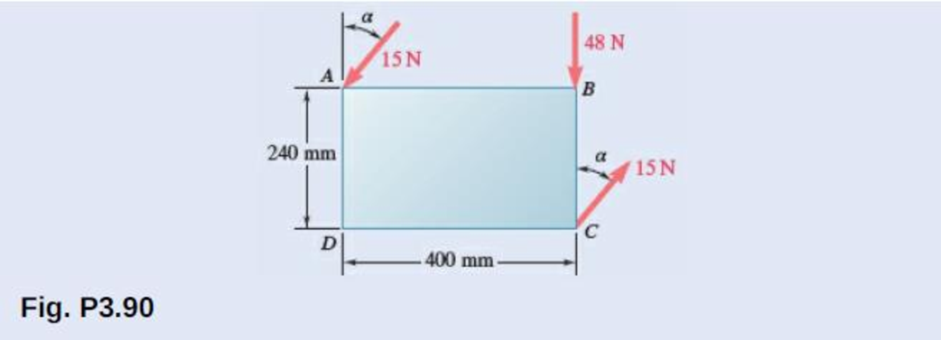
A rectangular plate is acted upon by the force and couple shown. This system is to be replaced with a single equivalent force. (a) For α = 40°, specify the magnitude and line of action of the equivalent force. (b) Specify the value of α if the line of action of the equivalent force is to intersect line CD 300 mm to the right of D.
Expert Solution & Answer
Want to see the full answer?
Check out a sample textbook solution
Students have asked these similar questions
Knowing that = 22° and Mc = 530 ft-lb, reduce the force-couple system shown to a single
equivalent force, and determine where the line of action of that force intersects member CB
measured from C. Enter the distance from C to the line of action of the single equivalent force below
in ft to the nearest 0.01 ft. Enter a positive number if the intersection is right of point C and al
negative number if the intersection is left of point C.
Mc
50 lb
150 lb
-3 ft-
B
2 ft
4 ft
PROBLEM 3
The force-couple system shown acts on a trapezoidal plate.
a. Determine the value of M, if the system shown is equivalent to a single force acting at point C.
b. The system shown is equivalent to a force-couple system consisting of R and M2 = 3000 kip-in
clockwise. If M, in this case is 120 kip-in counterclockwise, determine the point of action of the
resultant force Ralong line CD.
50°
1YZ kips
10 in
1X in
10 in
A
|20 kips
35 kips
8x kips
2Y in
M,
50°
1YZ kips
C
D
Parameters
X = 4, Y = 8, Z = 7
1X in
13 in
2Y in
24 in
8X kips
83 kips
145 kips
1YZ kips
18 in
The force and couple shown are to be replaced by an equivalent single force. Knowing that P=2Q , determine the required value of a if the line of action of the single equivalent force is to pass through (a) point A, (b) point C.
Chapter 3 Solutions
Vector Mechanics for Engineers: Statics and Dynamics
Ch. 3.1 - A foot valve for a pneumatic system is hinged at...Ch. 3.1 - 3.2A foot valve for a pneumatic system is hinged...Ch. 3.1 - It is known that a vertical force of 200 lb is...Ch. 3.1 - A 300-N force is applied at A as shown. Determine...Ch. 3.1 - A 300-N force is applied at A as shown. Determine...Ch. 3.1 - An 8-lb force P is applied to a shift lever....Ch. 3.1 - For the shift lever shown, determine the magnitude...Ch. 3.1 - An 11-lb force P is applied to a shift lever. The...Ch. 3.1 - Rod AB is held in place by the cord AC. Knowing...Ch. 3.1 - Rod AB is held in place by the cord AC. Knowing...
Ch. 3.1 - 3.11 and 3.12The tailgate of a car is supported by...Ch. 3.1 - 3.11 and 3.12The tailgate of a car is supported by...Ch. 3.1 - 3.13 and 3.14It is known that the connecting rod...Ch. 3.1 - 3.13 and 3.14It is known that the connecting rod...Ch. 3.1 - Form the vector product P1 P2 and use the result...Ch. 3.1 - The vectors P and Q are two adjacent sides of a...Ch. 3.1 - A plane contains the vectors A and B. Determine...Ch. 3.1 - A line passes through the points (4 m, 3 m) and (2...Ch. 3.1 - Prob. 3.19PCh. 3.1 - Determine the moment about the origin O of the...Ch. 3.1 - Before the trunk of a large tree is felled, cables...Ch. 3.1 - The 12-ft boom AB has a fixed end A. A steel cable...Ch. 3.1 - A 200-N force is applied as shown to the bracket...Ch. 3.1 - A force P of magnitude 200 N acts along the...Ch. 3.1 - A 6-ft-long fishing rod AB is securely anchored in...Ch. 3.1 - A precast concrete wall section is temporarily...Ch. 3.1 - In Prob. 3.22, determine the perpendicular...Ch. 3.1 - In Prob. 3.23, determine the perpendicular...Ch. 3.1 - In Prob. 3.24, determine the perpendicular...Ch. 3.1 - In Prob. 3.25, determine the perpendicular...Ch. 3.1 - In Prob. 3.25, determine the perpendicular...Ch. 3.1 - In Prob. 3.26, determine the perpendicular...Ch. 3.1 - In Prob. 3.26, determine the perpendicular...Ch. 3.1 - Determine the value of a that minimizes the...Ch. 3.2 - Given the vectors P = 2i + j + 2k, Q = 3i + 4j ...Ch. 3.2 - Form the scalar product B C and use the result...Ch. 3.2 - Three cables are attached to the top of the tower...Ch. 3.2 - Three cables are attached to the top of the tower...Ch. 3.2 - Knowing that the tension in cable AC is 280 lb,...Ch. 3.2 - Prob. 3.40PCh. 3.2 - Ropes AB and BC are two of the ropes used to...Ch. 3.2 - Prob. 3.42PCh. 3.2 - The 20-in. tube AB can slide along a horizontal...Ch. 3.2 - Solve Prob. 3.43 for the position corresponding to...Ch. 3.2 - Determine the volume of the parallelepiped of Fig....Ch. 3.2 - Given the vectors P = 3i + 2j + k, Q = 5i + j 2k,...Ch. 3.2 - A crane is oriented so that the end of the 25-m...Ch. 3.2 - 3.48The 25-m crane boom AO lies in the yz plane....Ch. 3.2 - To loosen a frozen valve, a force F with a...Ch. 3.2 - 3.50When a force F is applied to the handle of the...Ch. 3.2 - The 0.61 1.00-m lid ABCD of a storage bin is...Ch. 3.2 - 3.52The 0.61 1.00-m lid ABCD of a storage bin is...Ch. 3.2 - A farmer uses cables and winch pullers B and E to...Ch. 3.2 - Solve Prob. 3.53 when the tension in cable AB is...Ch. 3.2 - A force P of magnitude 520 lb acts on the frame...Ch. 3.2 - 3.56A force P acts on the frame shown at point E....Ch. 3.2 - The frame ACD is hinged at A and D and is...Ch. 3.2 - In Prob. 3.57, determine the moment about the...Ch. 3.2 - The triangular plate ABC is supported by...Ch. 3.2 - 3.60The triangular plate ABC is supported by...Ch. 3.2 - A regular tetrahedron has six edges of length a. A...Ch. 3.2 - Prob. 3.62PCh. 3.2 - Prob. 3.63PCh. 3.2 - In Prob. 3.55, determine the perpendicular...Ch. 3.2 - In Prob. 3.56, determine the perpendicular...Ch. 3.2 - In Prob. 3.57, determine the perpendicular...Ch. 3.2 - In Prob. 3.58, determine the perpendicular...Ch. 3.2 - In Prob. 3.59, determine the perpendicular...Ch. 3.2 - In Prob. 3.60, determine the perpendicular...Ch. 3.3 - Two 80-N forces are applied as shown to the...Ch. 3.3 - Two parallel 60-N forces are applied as shown to...Ch. 3.3 - A multiple-drilling machine is used to drill...Ch. 3.3 - Four pegs of the same diameter are attached to a...Ch. 3.3 - Prob. 3.74PCh. 3.3 - The shafts of an angle drive are acted upon by the...Ch. 3.3 - If P = 0 in the figure, replace the two remaining...Ch. 3.3 - 3.77If P = 20 lb in the figure, replace the three...Ch. 3.3 - The two couples shown are to be replaced with a...Ch. 3.3 - Solve part a of Prob. 3.78, assuming that two 15-N...Ch. 3.3 - Shafts A and B connect the gear box to the wheel...Ch. 3.3 - A 500-N force is applied to a bent plate as shown....Ch. 3.3 - Prob. 3.82PCh. 3.3 - Prob. 3.83PCh. 3.3 - A 30-lb vertical force P is applied at A to the...Ch. 3.3 - A worker tries to move a rock by applying a 360-N...Ch. 3.3 - A worker tries to move a rock by applying a 360-N...Ch. 3.3 - The shearing forces exerted on the cross section...Ch. 3.3 - Knowing that = 60, replace the force and couple...Ch. 3.3 - Three control rods attached to a lever ABC exert...Ch. 3.3 - A rectangular plate is acted upon by the force and...Ch. 3.3 - While tapping a hole, a machinist applies the...Ch. 3.3 - Prob. 3.92PCh. 3.3 - Replace the 250-kN force P with an equivalent...Ch. 3.3 - A 2.6-kip force is applied at point D of the...Ch. 3.3 - Prob. 3.95PCh. 3.3 - To keep a door closed, a wooden stick is wedged...Ch. 3.3 - A 46-lb force F and a 2120-lbin. couple M are...Ch. 3.3 - Prob. 3.98PCh. 3.3 - Prob. 3.99PCh. 3.3 - Prob. 3.100PCh. 3.4 - 3.101A 4-m-long beam is subjected to a variety of...Ch. 3.4 - A 4-m-long beam is loaded as shown. Determine the...Ch. 3.4 - Determine the single equivalent force and the...Ch. 3.4 - Five separate force-couple systems act at the...Ch. 3.4 - The weights of two children sitting at ends A and...Ch. 3.4 - Three stage lights are mounted on a pipe as shown....Ch. 3.4 - A beam supports three loads of given magnitude and...Ch. 3.4 - A 6 12-in. plate is subjected to four loads as...Ch. 3.4 - Gear C is rigidly attached to arm AB. If the...Ch. 3.4 - To test the strength of a 625 500-mm suitcase,...Ch. 3.4 - Prob. 3.111PCh. 3.4 - Prob. 3.112PCh. 3.4 - The roof of a building frame is subjected to the...Ch. 3.4 - Prob. 3.114PCh. 3.4 - A couple M and the three forces shown are applied...Ch. 3.4 - A machine component is subjected to the forces and...Ch. 3.4 - Prob. 3.117PCh. 3.4 - As follower AB rolls along the surface of member...Ch. 3.4 - A machine component is subjected to the forces...Ch. 3.4 - Two 150-mm-diameter pulleys are mounted on line...Ch. 3.4 - As an adjustable brace BC is used to bring a wall...Ch. 3.4 - In order to unscrew the tapped faucet A, a plumber...Ch. 3.4 - Prob. 3.123PCh. 3.4 - Four forces are applied to the machine component...Ch. 3.4 - A blade held in a brace is used to tighten a screw...Ch. 3.4 - A mechanic uses a crowfoot wrench to loosen a bolt...Ch. 3.4 - Four horizontal forces act on a vertical...Ch. 3.4 - Determine the magnitude of the force P for which...Ch. 3.4 - Prob. 3.129PCh. 3.4 - Prob. 3.130PCh. 3.4 - A concrete foundation mat of 5-m radius supports...Ch. 3.4 - Prob. 3.132PCh. 3.4 - Three forces of the same magnitude P act on a cube...Ch. 3.4 - A piece of sheet metal is bent into the shape...Ch. 3.4 - Prob. 3.135PCh. 3.4 - Prob. 3.136PCh. 3.4 - Two bolts at A and B are tightened by applying the...Ch. 3.4 - Two bolts at A and B are tightened by applying the...Ch. 3.4 - Prob. 3.139PCh. 3.4 - Prob. 3.140PCh. 3.4 - Prob. 3.141PCh. 3.4 - Prob. 3.142PCh. 3.4 - Replace the wrench shown with an equivalent system...Ch. 3.4 - Prob. 3.144PCh. 3.4 - Show that a wrench can be replaced with two...Ch. 3.4 - Show that a wrench can be replaced with two...Ch. 3 - A 300-N force P is applied at point A of the bell...Ch. 3 - A winch puller AB is used to straighten a fence...Ch. 3 - A small boat hangs from two davits, one of which...Ch. 3 - Prob. 3.150RPCh. 3 - A single force P acts at C in a direction...Ch. 3 - The 23-in. vertical rod CD is welded to the...Ch. 3 - In a manufacturing operation, three holes are...Ch. 3 - A 260-lb force is applied at A to the rolled-steel...Ch. 3 - The force and couple shown are to be replaced by...Ch. 3 - Prob. 3.156RPCh. 3 - Prob. 3.157RPCh. 3 - While using a pencil sharpener, a student applies...
Additional Engineering Textbook Solutions
Find more solutions based on key concepts
Determine the velocity of block D if end A of the rope is pulled down with a speed of vA = 3 m/s.
Engineering Mechanics: Dynamics (14th Edition)
Convert the following quantities from English to SI units: a. 98 Btu/(hr-ft-F) b. 0.24 Btu/(lbm-F) C. 0.04 Ibm/...
Heating Ventilating and Air Conditioning: Analysis and Design
What types of coolant are used in vehicles?
Automotive Technology: Principles, Diagnosis, and Service (5th Edition)
6–1C A mechanic claims to have developed a car engine that runs on water instead of gasoline. What is your resp...
Thermodynamics: An Engineering Approach
A biological fluid moves at a flow rate of m=0.02kg/s through a coiled, thin-walled, 5-mm-diameter tube submerg...
Fundamentals of Heat and Mass Transfer
What parts are included in the vehicle chassis?
Automotive Technology: Principles, Diagnosis, And Service (6th Edition) (halderman Automotive Series)
Knowledge Booster


Learn more about
Need a deep-dive on the concept behind this application? Look no further. Learn more about this topic, mechanical-engineering and related others by exploring similar questions and additional content below.Similar questions
- In opening a door which is equipped with a heavy- duty return mechanism, a person exerts a force P of magnitude 8 lb as shown. Force P and the normal n to the face of the door lie in a vertical plane. Ex- press P as a vector and determine the angles 0, 0y, and 0, which the line of action of P makes with the positive x-, y-, and z-axes. 40" P. 30° y 20°arrow_forwardForce P and couple M are applied at A as shown. 1. Suppose an equivalent system was made such that only force at B and a couple are present. What gives the magnitude of force at B and the couple in the equivalent system? 2. If the force P and couple M is to be replaced with a single force, where is the point of application of this single force along bar ABCD in order to have the same external effect as the original set of force P and couple M? (How many m to the left or right of B)arrow_forwardThe forces shown form a couple. Which ONE of the following equations can be used to replace the shown couple with an equivalent couple acting at points A and B. HINT: Choose clockwise as negative and counterclockwise as positive. 50 mm AB 40 N 200 mm 40 N Ⓒa. 40 N(200 mm) - F(50 mm) = 0 b. -40 N(200 mm) + F(50 mm) = c. +40 N(200 mm) + F(50 mm) = 0 d. 50 N(200 mm) - F(40 mm) = 0 e. 40 N(50 mm) - F(200 mm) = 0 Clear my choicearrow_forward
- The shearing forces exerted on the cross section of a steel channel can be represented by a 900-N vertical force and two 250-N horizontal forces as shown. Replace this force and couple with a single force F applied at point C , and determine the distance x from C to line BD . (Point Cis defined as the shear center of the section.)arrow_forward250 N 200 mm 20 mm E 40 mm 100 mm 50 N 160 mm 120 N 300 N Four forces are applied to the machine component ABDE as shown. Replace these forces with an equivalent force-couple system at A.arrow_forwardUsing the coordinate system shown, determine the components of the Moment vector (M) about the X, Y and Z axis, produced by the couple, if the magnitude of the force F is 75N 300 mm 200 mm F 150 mm B. 400 mm 200 mm Answer in (Nm) M, Choose... Choose... + М, Choose... +arrow_forward
- Q1: If the combined moment of the two forces about point C is zero, determine (a) The magnitude of the force P (b) The magnitude R of the resultant of the two forces, Specify the distance x from point O to the point on the x-axis through which the line of action of R passes. 120N 40 mm +P 40 mm 60° -x 40 mm C Q2. The original force and couple system and an equivalent force- couple system have the same -------- effect on a body. A) Internal B) External C) Internal and external D) Microscopicarrow_forward(a) Knowing that the magnitude of the moment of force P about line CD is 100 N-m, determine the magnitude of the force P. (b) Express the moment of force P about line CD as a Cartesian vector. (c) Find the magnitude of the moment of force P about point O. 600 mm 400 mm 300 mm 0 B D 350 mm Parrow_forwardA 20-lb force is applied to the control rod AB as shown. Knowing that the length of the rod is 9 in. and that α=25°, determine the moment of the force about point B by resolving the force into horizontal and vertical components.arrow_forward
- Situation 3. The force system shown consists of the couple C and four forces. If the resultant of this system is 75000 N-mm counterclockwise couple, determine P, Q and C. y 120 N 12 TA 5 C Q 30 mm P 400 N 3 Hle 30 mm Вarrow_forward4. The two couples shown are to be replaced with a single equivalent couple. Determine its magnitude and the direction of its axis. F= 100 lb 200 lb -F 30° F 1.5 ft 1.25 ft 130° 200 lbarrow_forwardQ1: If the combined moment of the two forces about point C is zero, determine (a) The magnitude of the force P (b) The magnitude R of the resultant of the two forces, Specify the distance x from point O to the point on the x-axis through which the line of action of R passes. 120N 40 mm 60° 40 mm 40 mm ctarrow_forward
arrow_back_ios
SEE MORE QUESTIONS
arrow_forward_ios
Recommended textbooks for you
 Elements Of ElectromagneticsMechanical EngineeringISBN:9780190698614Author:Sadiku, Matthew N. O.Publisher:Oxford University Press
 Mechanics of Materials (10th Edition)Mechanical EngineeringISBN:9780134319650Author:Russell C. HibbelerPublisher:PEARSON
 Thermodynamics: An Engineering ApproachMechanical EngineeringISBN:9781259822674Author:Yunus A. Cengel Dr., Michael A. BolesPublisher:McGraw-Hill Education
 Control Systems EngineeringMechanical EngineeringISBN:9781118170519Author:Norman S. NisePublisher:WILEY
 Mechanics of Materials (MindTap Course List)Mechanical EngineeringISBN:9781337093347Author:Barry J. Goodno, James M. GerePublisher:Cengage Learning
 Engineering Mechanics: StaticsMechanical EngineeringISBN:9781118807330Author:James L. Meriam, L. G. Kraige, J. N. BoltonPublisher:WILEY
Elements Of Electromagnetics
Mechanical Engineering
ISBN:9780190698614
Author:Sadiku, Matthew N. O.
Publisher:Oxford University Press
Mechanics of Materials (10th Edition)
Mechanical Engineering
ISBN:9780134319650
Author:Russell C. Hibbeler
Publisher:PEARSON
Thermodynamics: An Engineering Approach
Mechanical Engineering
ISBN:9781259822674
Author:Yunus A. Cengel Dr., Michael A. Boles
Publisher:McGraw-Hill Education
Control Systems Engineering
Mechanical Engineering
ISBN:9781118170519
Author:Norman S. Nise
Publisher:WILEY
Mechanics of Materials (MindTap Course List)
Mechanical Engineering
ISBN:9781337093347
Author:Barry J. Goodno, James M. Gere
Publisher:Cengage Learning
Engineering Mechanics: Statics
Mechanical Engineering
ISBN:9781118807330
Author:James L. Meriam, L. G. Kraige, J. N. Bolton
Publisher:WILEY
How to balance a see saw using moments example problem; Author: Engineer4Free;https://www.youtube.com/watch?v=d7tX37j-iHU;License: Standard Youtube License