
Mechanics of Materials
11th Edition
ISBN: 9780137605460
Author: Russell C. Hibbeler
Publisher: Pearson Education (US)
expand_more
expand_more
format_list_bulleted
Concept explainers
Videos
Textbook Question
Chapter 3.4, Problem 20P
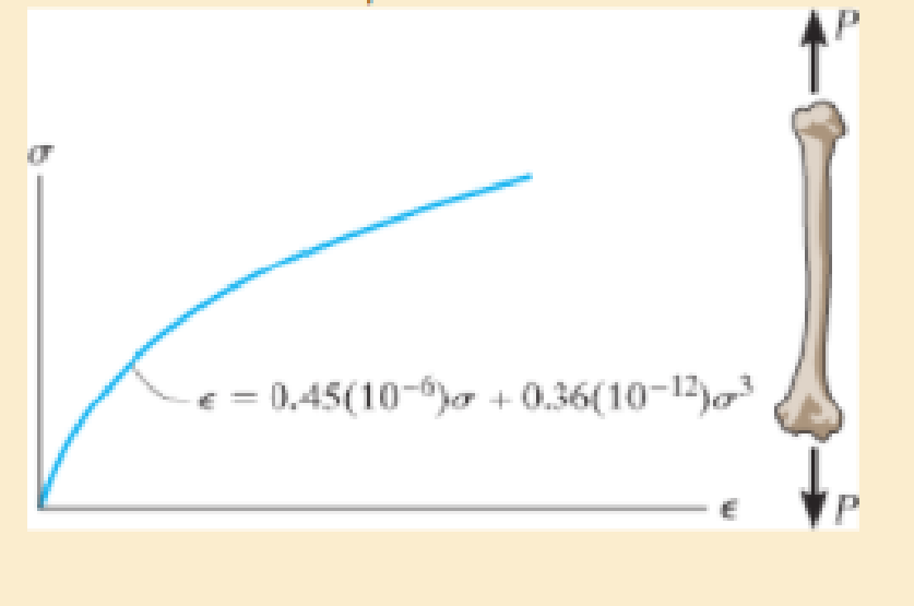
The stress-strain diagram for a bone is shown and can be described by the equation ε = 0.45 (10−6) σ + 0.36 (10−12) σ3 where σ is in kPa. Determine the modulus of toughness and the amount of elongation of a 200-mm-long region just before it fractures if failure occurs at ε = 0.12 mm/mm.
Prob. 3–20
Expert Solution & Answer
Want to see the full answer?
Check out a sample textbook solution
Students have asked these similar questions
3–26. The thin-walled tube is subjected to an axial force
of 40 kN. If the tube elongates 3 mm and its circumference
decreases 0.09 mm, determine the modulus of elasticity,
Poisson's ratio, and the shear modulus of the tube's
material. The material behaves elastically.
40 kN
900 mm
| 10 mm
40 kN
12.5 mm
The A-36 steel bar consists of two segments, one of a circular cross-section of radius r, and one of square cross-section. If the bar is subjected to the axial loading of P, determine the dimensions of the square segment so that the strain energy within the square segment is the same as in the circular segment.
F3-11. The material for the 50-mm-long specimen has the
stress-strain diagram shown. If P = 150 kN is applied and
then released, determine the permanent elongation of the
specimen.
P
20 mm
o (MPa)
200
P
500
450
e (mm/mm)
0.00225
0.03
F3-10/11
Chapter 3 Solutions
Mechanics of Materials
Ch. 3.4 - Define a homogeneous material.Ch. 3.4 - Indicate the points on the stress-strain diagram...Ch. 3.4 - Define the modulus of elasticity E.Ch. 3.4 - At room temperature, mild steel is a ductile...Ch. 3.4 - Engineering stress and strain are calculated using...Ch. 3.4 - As the temperature increases the modulus of...Ch. 3.4 - A 100-mm-long rod has a diameter of 15 mm. If an...Ch. 3.4 - A bar has a length of 8 in. and cross-sectional...Ch. 3.4 - A 10-mm-diameter rod has a modulus of elasticity...Ch. 3.4 - The material for the 50-mm-long specimen has the...
Ch. 3.4 - The material for the 50-mm-long specimen has the...Ch. 3.4 - If the elongation of wire BC is 0.2 mm after the...Ch. 3.4 - Data taken from a stress-strain test for a ceramic...Ch. 3.4 - The stress-strain diagram for a steel alloy having...Ch. 3.4 - The stress-strain diagram for a steel alloy having...Ch. 3.4 - The stress-strain diagram for a steel alloy having...Ch. 3.4 - Determine the elongation of the square hollow bar...Ch. 3.4 - The stress-strain diagram for an aluminum alloy...Ch. 3.4 - The stress-strain diagram for an aluminum alloy...Ch. 3.4 - The stress-strain diagram for an aluminum alloy...Ch. 3.4 - A structural member in a nuclear reactor is made...Ch. 3.4 - The rigid pipe is supported by a pin at A and an...Ch. 3.4 - The rigid pipe is supported by a pin at A and an...Ch. 3.4 - Direct tension indicators are sometimes used...Ch. 3.4 - A tension test was performed on a magnesium alloy...Ch. 3.4 - The stress-strain diagram for a bone is shown and...Ch. 3.4 - The two bars are made of a material that has the...Ch. 3.4 - The two bars are made of a material that has the...Ch. 3.7 - A 100-mm-long rod has a diameter of 15 mm. If an...Ch. 3.7 - A solid circular rod that is 600 mm long and 20 mm...Ch. 3.7 - A 20-mm-wide block is firmly bonded to rigid...Ch. 3.7 - A 20-mm-wide block is bonded to rigid plates at...Ch. 3.7 - The acrylic plastic rod is 400mm long and 20mm in...Ch. 3.7 - The elastic portion of the stress-strain diagram...Ch. 3.7 - The elastic portion of the stress-strain diagram...Ch. 3.7 - The lap joint is connected together using a 1.25...Ch. 3.7 - The lap joint is connected together using a 1.25...Ch. 3.7 - Prob. 32PCh. 3.7 - The thin-walled tube is subjected to an axial...Ch. 3 - The elastic portion of the tension stress-strain...Ch. 3 - The elastic portion of the tension stress-strain...Ch. 3 - The rigid beam rests in the horizontal position on...Ch. 3 - The wires each have a diameter of 12 in., length...Ch. 3 - Prob. 5RPCh. 3 - diameter steel bolts. If the clamping force in...Ch. 3 - The stress-strain diagram for polyethylene, which...Ch. 3 - The pipe with two rigid caps attached to its ends...Ch. 3 - The 8-mm-diameter bolt is made of an aluminum...Ch. 3 - An acetal polymer block is fixed to the rigid...
Knowledge Booster


Learn more about
Need a deep-dive on the concept behind this application? Look no further. Learn more about this topic, mechanical-engineering and related others by exploring similar questions and additional content below.Similar questions
- 8-21. The elastic portion of the stress-strain diagram for an aluminum alloy is shown in the figure. The specimen from which it was obtained has an original diameter of 12.7 mm and a gage length of 50.8 mm. When the applied load on the specimen is 50 kN, the diameter is 12.67494 mm. Determine Poisson's ratio for the material. (MPa) 490 (mm/mm) 0.007arrow_forward8-22. The elastic portion of the stress-strain diagram for an aluminum alloy is shown in the figure. The specimen from which it was obtained has an original diameter of 12.7 mm and a gage length of 50.8 mm. If a load of P - 60 kN is applied to the specimen, determine its new diameter and length. Take v-0.35. a (MPa) 490 (mm/mm) 0.007arrow_forwardA force P and a force Q, applied via a nut, are acting on the arm attached to the end of a shaft made of steel. The strain gauge readings on point A of the shaft show the following deformation values: ε1 = 630x10-6, ε2 = 600x10-6, and ε3 = - 189x10-6. Determine the magnitudes of the applied forces P and Q (E = 200 GPa, υ = 0.3).arrow_forward
- The rod is 200 mm long and 60 mm in diameter. If an axial load of 300 N is applied to it, determine the change in its length, the change in its diameter, normal stress and normal strain. The Poisson's ratio is 0.4 and the modulus of elasticity is 20 GPa.arrow_forward*3-28. The elastic portion of the stress-strain diagram for a steel alloy is shown in the figure. The specimen from which it was obtained had an original diameter of 13 mm and a gauge length of 50 mm. If a load of P- 20 kN is applied to the specimen, determine its diameter and gauge length. Take v - 0.4. o(MPa) 400 e(mm/mm) 0.002arrow_forwardF8-10. The material for the 50-mm-long specimen has the stress-strain diagram shown. If P - 100 kN, determine the elongation of the specimen. a (MPa) 20 mm 500 450 e (mm/mm) 0.00225 0.03arrow_forward
- The steel shaft has a radius of 50mm. Determine the torque (T) applied to the shaft if the two strain gages attached to the shaft surface record the deformations ex -80 (10-6) and ey ' : = 80 (10-6). Take E = 200 GPa, v = 0.3. | 45° UTarrow_forwardIn its undeformed state the assembly is represented by A-B-C-D, with theta = 0.53 in radians. The deformed shape is: A’-B’-C’-D. The deformation is such that the normal strain in AB is: ϵAB = 0.033 and that in CB is: ϵCB=0.031. Calculate the normal strain in BD (correctly up to four decimal places) neglecting the higher-order contributions due to the normal strains in AB and CB.arrow_forwardA tri-axial state of stress, σx , σy, and σz ,exists in a steel machine part. For steel, E = 200GPa and ν = 0.3. Determine the normal strain in the x-direction if σx = 100MPa, σy = 35MPa, σz = 70MPa. Determine the dilatation. Determine the modulus of rigidity.arrow_forward
- The specimen shown has been cut from a 5-mm-thick sheet of vinyl (E= 3.10 GPa) and is subjected to a 1.5-kN tensile load. It is given that /= 58 mm. Dimensions in mm A в 10 D P'= 1.5 kN P = 1.5 kN 25 25 - 40- Determine the total deformation of the specimen. The total deformation of the specimen is mm.arrow_forward8-21. The elastic portion of the stress-strain diagram for an aluminum alloy is shown in the figure. The specimen from which it was obtained has an original diameter of 12.7 mm and a gage length of 50.8 mm. When the applied load on the specimen is 50 kN, the diameter is 12.67494 mm. Determine Poisson's ratio for the material. 8-22. The elastic portion of the stress-strain diagram for an aluminum alloy is shown in the figure. The specimen from which it was obtained has an original diameter of 12.7 mm and a gage length of 50.8 mm. If a load of P = 60 kN is applied to the specimen, determine its new diameter and length. Take v = 0.35. σ (MPa) 490 0.007 Probs. 8-21/22 € (mm/mm)arrow_forward*3-12. Fiberglass has a stress-strain diagram as shown. If a 50-mm-diameter bar of length 2 m made from this material is subjected to an axial tensile load of 60 kN, determine its elongation. σ (Pa) 300(10%) 1/2 €(mm/mm)arrow_forward
arrow_back_ios
SEE MORE QUESTIONS
arrow_forward_ios
Recommended textbooks for you
 Elements Of ElectromagneticsMechanical EngineeringISBN:9780190698614Author:Sadiku, Matthew N. O.Publisher:Oxford University Press
 Mechanics of Materials (10th Edition)Mechanical EngineeringISBN:9780134319650Author:Russell C. HibbelerPublisher:PEARSON
 Thermodynamics: An Engineering ApproachMechanical EngineeringISBN:9781259822674Author:Yunus A. Cengel Dr., Michael A. BolesPublisher:McGraw-Hill Education
 Control Systems EngineeringMechanical EngineeringISBN:9781118170519Author:Norman S. NisePublisher:WILEY
 Mechanics of Materials (MindTap Course List)Mechanical EngineeringISBN:9781337093347Author:Barry J. Goodno, James M. GerePublisher:Cengage Learning
 Engineering Mechanics: StaticsMechanical EngineeringISBN:9781118807330Author:James L. Meriam, L. G. Kraige, J. N. BoltonPublisher:WILEY
Elements Of Electromagnetics
Mechanical Engineering
ISBN:9780190698614
Author:Sadiku, Matthew N. O.
Publisher:Oxford University Press
Mechanics of Materials (10th Edition)
Mechanical Engineering
ISBN:9780134319650
Author:Russell C. Hibbeler
Publisher:PEARSON
Thermodynamics: An Engineering Approach
Mechanical Engineering
ISBN:9781259822674
Author:Yunus A. Cengel Dr., Michael A. Boles
Publisher:McGraw-Hill Education
Control Systems Engineering
Mechanical Engineering
ISBN:9781118170519
Author:Norman S. Nise
Publisher:WILEY
Mechanics of Materials (MindTap Course List)
Mechanical Engineering
ISBN:9781337093347
Author:Barry J. Goodno, James M. Gere
Publisher:Cengage Learning
Engineering Mechanics: Statics
Mechanical Engineering
ISBN:9781118807330
Author:James L. Meriam, L. G. Kraige, J. N. Bolton
Publisher:WILEY
EVERYTHING on Axial Loading Normal Stress in 10 MINUTES - Mechanics of Materials; Author: Less Boring Lectures;https://www.youtube.com/watch?v=jQ-fNqZWrNg;License: Standard YouTube License, CC-BY