
Mechanics of Materials
11th Edition
ISBN: 9780137605460
Author: Russell C. Hibbeler
Publisher: Pearson Education (US)
expand_more
expand_more
format_list_bulleted
Videos
Textbook Question
Chapter 3.4, Problem 5P
The stress-strain diagram for a steel alloy having an original diameter of 0.5 in. and a gage length of 2 in. is given in the figure. If the specimen is loaded until it is stressed to 70 ksi, determine the approximate amount of elastic recovery and the increase in the gage length after it is unloaded.
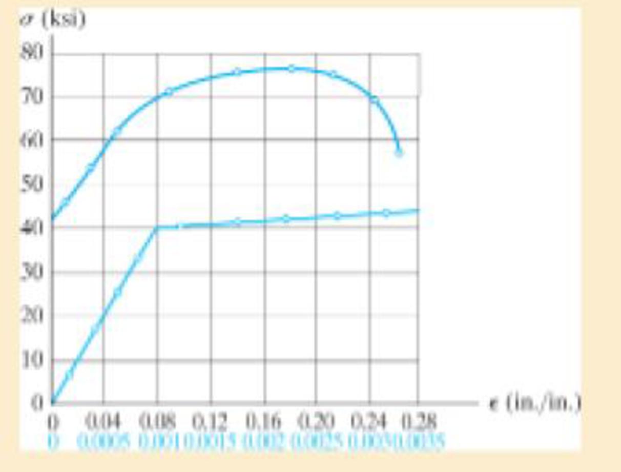
Prob. 3–5
Expert Solution & Answer
Want to see the full answer?
Check out a sample textbook solution
Students have asked these similar questions
3–26. The thin-walled tube is subjected to an axial force
of 40 kN. If the tube elongates 3 mm and its circumference
decreases 0.09 mm, determine the modulus of elasticity,
Poisson's ratio, and the shear modulus of the tube's
material. The material behaves elastically.
40 kN
900 mm
| 10 mm
40 kN
12.5 mm
*3-28. The elastic portion of the stress-strain diagram for
a steel alloy is shown in the figure. The specimen from
which it was obtained had an original diameter of 13 mm
and a gauge length of 50 mm. If a load of P- 20 kN is
applied to the specimen, determine its diameter and gauge
length. Take v - 0.4.
o(MPa)
400
e(mm/mm)
0.002
8-21. The elastic portion of the stress-strain diagram for
an aluminum alloy is shown in the figure. The specimen
from which it was obtained has an original diameter of
12.7 mm and a gage length of 50.8 mm. When the applied
load on the specimen is 50 kN, the diameter is 12.67494 mm.
Determine Poisson's ratio for the material.
8-22. The elastic portion of the stress-strain diagram for an
aluminum alloy is shown in the figure. The specimen from
which it was obtained has an original diameter of 12.7 mm
and a gage length of 50.8 mm. If a load of P = 60 kN is
applied to the specimen, determine its new diameter and
length. Take v = 0.35.
σ (MPa)
490
0.007
Probs. 8-21/22
€ (mm/mm)
Chapter 3 Solutions
Mechanics of Materials
Ch. 3.4 - Define a homogeneous material.Ch. 3.4 - Indicate the points on the stress-strain diagram...Ch. 3.4 - Define the modulus of elasticity E.Ch. 3.4 - At room temperature, mild steel is a ductile...Ch. 3.4 - Engineering stress and strain are calculated using...Ch. 3.4 - As the temperature increases the modulus of...Ch. 3.4 - A 100-mm-long rod has a diameter of 15 mm. If an...Ch. 3.4 - A bar has a length of 8 in. and cross-sectional...Ch. 3.4 - A 10-mm-diameter rod has a modulus of elasticity...Ch. 3.4 - The material for the 50-mm-long specimen has the...
Ch. 3.4 - The material for the 50-mm-long specimen has the...Ch. 3.4 - If the elongation of wire BC is 0.2 mm after the...Ch. 3.4 - Data taken from a stress-strain test for a ceramic...Ch. 3.4 - The stress-strain diagram for a steel alloy having...Ch. 3.4 - The stress-strain diagram for a steel alloy having...Ch. 3.4 - The stress-strain diagram for a steel alloy having...Ch. 3.4 - Determine the elongation of the square hollow bar...Ch. 3.4 - The stress-strain diagram for an aluminum alloy...Ch. 3.4 - The stress-strain diagram for an aluminum alloy...Ch. 3.4 - The stress-strain diagram for an aluminum alloy...Ch. 3.4 - A structural member in a nuclear reactor is made...Ch. 3.4 - The rigid pipe is supported by a pin at A and an...Ch. 3.4 - The rigid pipe is supported by a pin at A and an...Ch. 3.4 - Direct tension indicators are sometimes used...Ch. 3.4 - A tension test was performed on a magnesium alloy...Ch. 3.4 - The stress-strain diagram for a bone is shown and...Ch. 3.4 - The two bars are made of a material that has the...Ch. 3.4 - The two bars are made of a material that has the...Ch. 3.7 - A 100-mm-long rod has a diameter of 15 mm. If an...Ch. 3.7 - A solid circular rod that is 600 mm long and 20 mm...Ch. 3.7 - A 20-mm-wide block is firmly bonded to rigid...Ch. 3.7 - A 20-mm-wide block is bonded to rigid plates at...Ch. 3.7 - The acrylic plastic rod is 400mm long and 20mm in...Ch. 3.7 - The elastic portion of the stress-strain diagram...Ch. 3.7 - The elastic portion of the stress-strain diagram...Ch. 3.7 - The lap joint is connected together using a 1.25...Ch. 3.7 - The lap joint is connected together using a 1.25...Ch. 3.7 - Prob. 32PCh. 3.7 - The thin-walled tube is subjected to an axial...Ch. 3 - The elastic portion of the tension stress-strain...Ch. 3 - The elastic portion of the tension stress-strain...Ch. 3 - The rigid beam rests in the horizontal position on...Ch. 3 - The wires each have a diameter of 12 in., length...Ch. 3 - Prob. 5RPCh. 3 - diameter steel bolts. If the clamping force in...Ch. 3 - The stress-strain diagram for polyethylene, which...Ch. 3 - The pipe with two rigid caps attached to its ends...Ch. 3 - The 8-mm-diameter bolt is made of an aluminum...Ch. 3 - An acetal polymer block is fixed to the rigid...
Knowledge Booster


Learn more about
Need a deep-dive on the concept behind this application? Look no further. Learn more about this topic, mechanical-engineering and related others by exploring similar questions and additional content below.Similar questions
- 8-22. The elastic portion of the stress-strain diagram for an aluminum alloy is shown in the figure. The specimen from which it was obtained has an original diameter of 12.7 mm and a gage length of 50.8 mm. If a load of P - 60 kN is applied to the specimen, determine its new diameter and length. Take v-0.35. a (MPa) 490 (mm/mm) 0.007arrow_forwardThe elastic portion of the stress-strain diagram for an aluminum alloy is shown in the figure. The specimen from which it was obtained has an original diameter of 12.7 mm and a gage length of 50.8 mm. If a load of P=60 kN is applied to the specimen, determine its new diameter and length. Take v = 0.35. o (MPa) 490 e (mm/mm) 0.007arrow_forwardThe elastic portion of the tension stress–strain diagram for an aluminum alloy is shown in the figure. The specimen used for the test has a gage length of 2 in. and a diameter of 0.5 in. If the applied load is 10 kip, determine the new diameter of the specimen. The shear modulus is Gal = 3.811032 ksi.arrow_forward
- The elastic portion of the stress–strain diagram for an aluminum alloy is shown in the figure. The specimen from which it was obtained has an original diameter of 12.7 mm and a gage length of 50.8 mm. If a load of P = 60 kN is applied to the specimen, determine its new diameter and length. Taken = 0.35.arrow_forwardThe strain at a point is 780x10-6 in the x, 400x10-5 in the y and -500x10-6 in the z direction. Determine the stress state if the Young's modulus is 10,640 ksi and v = 0.33.arrow_forward= 2-Consider a 45° off-axis tensile test coupon. Three strain gages attached as shown below are reading el 0.00647, 2= -0.00324, and 3 = 0.008095 at stress level of ox=100 MPa. Determine the off-axis modulus of elasticity Ex the off-axis major Poisson's ratio vxy and coefficient of mutual influence of the second kind nxy,x 2 √²-01-² y 45° €2 0₂arrow_forward
- The rigid bar ABC pivots about support B. After application of load P, end C of the rigid bar moves upward by 0.07 in. If the length of bar (1) is L₁-41 in, determine the average normal strain in bar (1). Assume that a-135 in, b-39 in, and c-0.15 in a b C Rigid bar 4 Part 1 * Incorrect Determine the distance that end A of the rigid bar moves downward, if end C moves upward by 0.07 in Answer: in VA i 00361arrow_forwardAn element of material in plain strain is subjected to strains x = 0.0015, , y . = -0.0002, and xy = 0.0003. (a) Determine the strains for an element oriented at an angle = 20°. (b) Determine the principal strains of the element. Confirm the solution using Mohr’s circle for plane strain.arrow_forwardAn element of material in plain strain is subjected to shear strain xy = 0.0003. (a) Determine the strains for an element oriented at an angle = 30°. (b) Determine the principal strains of the clement. Confirm the solution using Mohr’s circle for plane strain.arrow_forward
- 1 A rectangular steel plate with thickness t = 5/8 in. is subjected to uniform normal stresses a and ., as shown in the figure. Strain gages A and B. oriented in the x and v directions. respectively, arc attached to the plate. The gage readings give normal strains = 0.00065 (elongation) and £. = 0.00040 (elongation). Knowing that E = 30 X 106 psi and v = 0.3, determine the stresses c7 and a, and the change .11 in the thickness of the plate.arrow_forwardA strain rosette (see figure) mounted on the surface of an automobile frame gives the following readings: gage A,310 × 10-6:gage B,180 × l0-6; and gage C. -160 × 10-6. Determine the principal strains and maximum shear strains, and show them on sketches of properly oriented elements.arrow_forwardAn element of material in plain strain has the following strains: x = 0.001 and y = 0.0015. (a) Determine the strains for an element oriented at an angle = 250. (b) Find the principal strains of the element. Confirm the solution using Mohr’s circle for plane strain.arrow_forward
arrow_back_ios
SEE MORE QUESTIONS
arrow_forward_ios
Recommended textbooks for you
 Mechanics of Materials (MindTap Course List)Mechanical EngineeringISBN:9781337093347Author:Barry J. Goodno, James M. GerePublisher:Cengage Learning
Mechanics of Materials (MindTap Course List)
Mechanical Engineering
ISBN:9781337093347
Author:Barry J. Goodno, James M. Gere
Publisher:Cengage Learning
Lec21, Part 5, Strain transformation; Author: Mechanics of Materials (Libre);https://www.youtube.com/watch?v=sgJvz5j_ubM;License: Standard Youtube License