
Loose Leaf for Engineering Circuit Analysis Format: Loose-leaf
9th Edition
ISBN: 9781259989452
Author: Hayt
Publisher: Mcgraw Hill Publishers
expand_more
expand_more
format_list_bulleted
Videos
Textbook Question
Chapter 3.8, Problem 17P
In the circuit of Fig. 3.40, use resistance combination methods and current division to find i1, i2, and v3.
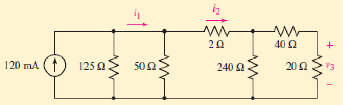
FIGURE 3.40
Expert Solution & Answer
Want to see the full answer?
Check out a sample textbook solution
Students have asked these similar questions
Electrical Engineering
For the final problem, consider the following circuit diagram:
12 Q
30 V
Vx
60 Q
2"Vx
B
6) For this circuit, please find and draw:
a. The Thevenin equivalent circuit between A and B, using external excitation to find R.
b. The Norton cquivalent circuit berween A and B.
c. Review section 3-8 from the text. What value load resistor connected between A and B would yield
maximum power transfer? How much power woukd this be?
mponent of nódal
ch element. There is no way of knowing the current through
wever, KCL must be satisfied at a sunernode like any other node. Hence a tde
spernode in Fig. 3.5,
i + i4 = i2 + i3
(3.11a)
v1 - v2
v1 - v3
v2 – 0
v3 - 0
(3.11b)
6.
To apply Kirchhoff's voltage law to the supernode in Fig. 3.4 we redraw the circuit as
shown in Fig. 3.5. Going around the loop in the clockwise»direction gives
-V2 + 5 + v3 = 0=v2 – V3 = 5
(3.12)
From Eqs. (3.10), (3.11b), and (3.12), we obtain the node volltages.
5V
د مُسق ک من ؤ
Figure 3.5 Applying KVL to a supernode.
Example 3.2: For the circuit shown in Fig. 3.6, find the node voltages.
Solution:
The supernode contains the 2-V source, nodes 1 and
10 2
www
2, and the 10-2 resistor. Applying KCL to the
2 V
supernode as shown in Fig. 3.7(a) gives
2.
12
2 = i + iz +7
7 A
Expressing in and iz in terms of the node voltages
2 A
22
v1 - 0
v2 - 0
2 =
7
4
or
(3.2.1)
V2 =-20 - 2vVI
Figure 3.6 For Example 3.2.
ESTHRER: ALI SHARAAN
METHORS OF ANALYSIS…
3b
For the circuit in Figure Q3(b), solve for Ix, Iy and Vz using superposition method.
Chapter 3 Solutions
Loose Leaf for Engineering Circuit Analysis Format: Loose-leaf
Ch. 3.2 - 3.1 (a) Count the number of branches and nodes in...Ch. 3.3 - Determine ix and vx in the circuit of Fig. 3.7....Ch. 3.3 - For the circuit of Fig. 3.9, if vR1=1V, determine...Ch. 3.3 - Determine vx in the circuit of Fig. 3.11.Ch. 3.4 - In the circuit of Fig. 3.12b, vs1 = 120 V, vs2 =...Ch. 3.4 - 3.6 In the circuit of Fig. 3.14, find the power...Ch. 3.5 - Determine v in the circuit of Fig. 3.16.Ch. 3.5 - For the single-node-pair circuit of Fig. 3.18,...Ch. 3.6 - Determine the current i in the circuit of Fig....Ch. 3.6 - Determine the voltage v in the circuit of Fig....
Ch. 3.6 - Determine whether the circuit of Fig. 3.25...Ch. 3.7 - 3.12 Determine a single-value equivalent...Ch. 3.7 - 3.13 Determine i in the circuit of Fig. 3.29....Ch. 3.7 - Determine v in the circuit of Fig. 3.31 by first...Ch. 3.7 - 3.15 For the circuit of Fig. 3.33, calculate the...Ch. 3.8 - 3.16 Use voltage division to determine vx in the...Ch. 3.8 - In the circuit of Fig. 3.40, use resistance...Ch. 3 - Referring to the circuit depicted in Fig. 3.45,...Ch. 3 - Referring to the circuit depicted in Fig. 3.46,...Ch. 3 - For the circuit of Fig. 3.47: (a) Count the number...Ch. 3 - For the circuit of Fig. 3.47: (a) Count the number...Ch. 3 - Refer to the circuit of Fig. 3.48, and answer the...Ch. 3 - A local restaurant has a neon sign constructed...Ch. 3 - Referring to the single-node diagram of Fig. 3.50,...Ch. 3 - Determine the current labeled I in each of the...Ch. 3 - In the circuit shown in Fig. 3.52, the resistor...Ch. 3 - The circuit of Fig. 3.53 represents a system...Ch. 3 - In the circuit depicted in Fig. 3.54, ix is...Ch. 3 - For the circuit of Fig. 3.55 (which employs a...Ch. 3 - Determine the current labeled I3 in the circuit of...Ch. 3 - Study the circuit depicted in Fig. 3.57, and...Ch. 3 - Prob. 15ECh. 3 - For the circuit of Fig. 3.58: (a) Determine the...Ch. 3 - For each of the circuits in Fig. 3.59, determine...Ch. 3 - Use KVL to obtain a numerical value for the...Ch. 3 - Prob. 19ECh. 3 - In the circuit of Fig. 3.55, calculate the voltage...Ch. 3 - Determine the value of vx as labeled in the...Ch. 3 - Consider the simple circuit shown in Fig. 3.63....Ch. 3 - (a) Determine a numerical value for each current...Ch. 3 - The circuit shown in Fig. 3.65 includes a device...Ch. 3 - The circuit of Fig. 3.12b is constructed with the...Ch. 3 - Obtain a numerical value for the power absorbed by...Ch. 3 - Compute the power absorbed by each element of the...Ch. 3 - Compute the power absorbed by each element in the...Ch. 3 - Kirchhoffs laws apply whether or not Ohms law...Ch. 3 - Referring to the circuit of Fig. 3.70, (a)...Ch. 3 - Determine a value for the voltage v as labeled in...Ch. 3 - Referring to the circuit depicted in Fig. 3.72,...Ch. 3 - Determine the voltage v as labeled in Fig. 3.73,...Ch. 3 - Although drawn so that it may not appear obvious...Ch. 3 - Determine the numerical value for veq in Fig....Ch. 3 - Determine the numerical value for ieq in Fig....Ch. 3 - For the circuit presented in Fig. 3.76. determine...Ch. 3 - Determine the value of v1 required to obtain a...Ch. 3 - (a) For the circuit of Fig. 3.78, determine the...Ch. 3 - What value of IS in the circuit of Fig. 3.79 will...Ch. 3 - (a) Determine the values for IX and VY in the...Ch. 3 - Determine the equivalent resistance of each of the...Ch. 3 - For each network depicted in Fig. 3.82, determine...Ch. 3 - (a) Simplify the circuit of Fig. 3.83 as much as...Ch. 3 - (a) Simplify the circuit of Fig. 3.84, using...Ch. 3 - Making appropriate use of resistor combination...Ch. 3 - Calculate the voltage labeled vx in the circuit of...Ch. 3 - Determine the power absorbed by the 15 resistor...Ch. 3 - Calculate the equivalent resistance Req of the...Ch. 3 - Show how to combine four 100 resistors to obtain...Ch. 3 - Prob. 51ECh. 3 - Prob. 52ECh. 3 - Prob. 53ECh. 3 - Prob. 54ECh. 3 - Prob. 55ECh. 3 - Prob. 56ECh. 3 - Prob. 57ECh. 3 - Prob. 58ECh. 3 - Prob. 59ECh. 3 - Prob. 60ECh. 3 - With regard to the circuit shown in Fig. 3.98,...Ch. 3 - Delete the leftmost 10 resistor in the circuit of...Ch. 3 - Consider the seven-element circuit depicted in...
Knowledge Booster


Learn more about
Need a deep-dive on the concept behind this application? Look no further. Learn more about this topic, electrical-engineering and related others by exploring similar questions and additional content below.Similar questions
- In the circuit of figure 3.22 R=0 and i1 and i2 are unknown, calculate i and VACarrow_forward1st Stage! FundamentaisS Of Electrical Engineering Chapter 3- Kirchhoff's laws 3.3 Homework: 1- Use KCL to obtain currents i,, i2, and iz in the circuit shown in below figure. 12 mA 8 mA i3 2- Find il, i2, and i3 in the circuit in Figure below.arrow_forwardQ.1/ Using Kirchoff's laws. Find the currents and voltages for the circuit shown in Figure 1. Q.2/A/ For the circuit shown in Figure 2, find Va, Vb, and Vc. Q.2/B/ Calculate the equivalent resistance Rab for the circuit shown in Figure 3. 8 ohm la 4 RI 2 R7 Ib Il Vi RI R8 V5 6 ohm R2 R3 3 ohm R9 30 V R5 60 V 1 ohm 3 ohm R4 R52 (Figure 1) (Figure 2) 10 ohm 1 ohm ohm 1 ohm 6 ohm 4 ohm ohx 5 ohm ohm 3 ohm 12 ohm (Figure 3)arrow_forward
- Write the Loop-current equations for the circuit below. Then, determine the values of i, iz and i3. 50 10 30 V 15 V wwarrow_forwardQ3. Obtain vo in the circuit of Figure Q3. 30 V 20 V 4 k2 2 k2 5 k2 Figure Q3 ww-arrow_forwardConsider the circuit diagram below. Given I = 2.5 mA and Is = 1.25 mA: a) Find the currents Is2, I2, I3, I4 and Iz. State your conclusion as a table of values. b) What is the voltage drop across R7? c) If Vab = 2.75 V, what is the value of Rs?arrow_forward
- Q2/ Find the state-space representation of the electrical network shown in Figure 3.8. The output is vo(t). C₁ R не Vo(1) L 0000arrow_forward3. A voltage source with internal resistance, 40 and load resistance, 60 is shown in figure 3. 50 V RL=60 B Figure 3 Using source transformation find the equivalent current source.arrow_forwarda) For the circuit shown in Figure (3.a), find i, using any method. 9kQ 12kn 12k0 6kQ 12v 6varrow_forward
- Find the Thevenin equivalent circuit external to RL from the network shown in Figure 3.1 below. Find then the load current IL. Find then the maximum power that can transfer to the RL. R₁=69 www a b ömö R₁=20 R3=30 www R2=1292 www R4=40 Figure 3.1 I 7Aarrow_forward3.71 Find mesh currents I1, I3, I, and I, and node voltages V, V2» and V, in the circuit shown in Figure P3.71. FIGURE P3.71 R, V, R2 1.25 kn 5 kN v/2500 12 R3 V3 R4 V2 10 k2 1 kN R5 1 kN R6 Vs 13 7.5 kn 14 20 Varrow_forward8V For the network of Figure Q3, determine: a) Ir b) Ve c) Vr 2.2 k2 1.8 ka +10Varrow_forward
arrow_back_ios
SEE MORE QUESTIONS
arrow_forward_ios
Recommended textbooks for you
 Introductory Circuit Analysis (13th Edition)Electrical EngineeringISBN:9780133923605Author:Robert L. BoylestadPublisher:PEARSON
 Delmar's Standard Textbook Of ElectricityElectrical EngineeringISBN:9781337900348Author:Stephen L. HermanPublisher:Cengage Learning
 Programmable Logic ControllersElectrical EngineeringISBN:9780073373843Author:Frank D. PetruzellaPublisher:McGraw-Hill Education
 Fundamentals of Electric CircuitsElectrical EngineeringISBN:9780078028229Author:Charles K Alexander, Matthew SadikuPublisher:McGraw-Hill Education
 Electric Circuits. (11th Edition)Electrical EngineeringISBN:9780134746968Author:James W. Nilsson, Susan RiedelPublisher:PEARSON
 Engineering ElectromagneticsElectrical EngineeringISBN:9780078028151Author:Hayt, William H. (william Hart), Jr, BUCK, John A.Publisher:Mcgraw-hill Education,
Introductory Circuit Analysis (13th Edition)
Electrical Engineering
ISBN:9780133923605
Author:Robert L. Boylestad
Publisher:PEARSON
Delmar's Standard Textbook Of Electricity
Electrical Engineering
ISBN:9781337900348
Author:Stephen L. Herman
Publisher:Cengage Learning
Programmable Logic Controllers
Electrical Engineering
ISBN:9780073373843
Author:Frank D. Petruzella
Publisher:McGraw-Hill Education
Fundamentals of Electric Circuits
Electrical Engineering
ISBN:9780078028229
Author:Charles K Alexander, Matthew Sadiku
Publisher:McGraw-Hill Education
Electric Circuits. (11th Edition)
Electrical Engineering
ISBN:9780134746968
Author:James W. Nilsson, Susan Riedel
Publisher:PEARSON
Engineering Electromagnetics
Electrical Engineering
ISBN:9780078028151
Author:Hayt, William H. (william Hart), Jr, BUCK, John A.
Publisher:Mcgraw-hill Education,
Mesh Current Problems in Circuit Analysis - Electrical Circuits Crash Course - Beginners Electronics; Author: Math and Science;https://www.youtube.com/watch?v=DYg8B-ElK0s;License: Standard Youtube License