
Shigley's Mechanical Engineering Design (McGraw-Hill Series in Mechanical Engineering)
10th Edition
ISBN: 9780073398204
Author: Richard G Budynas, Keith J Nisbett
Publisher: McGraw-Hill Education
expand_more
expand_more
format_list_bulleted
Concept explainers
Videos
Textbook Question
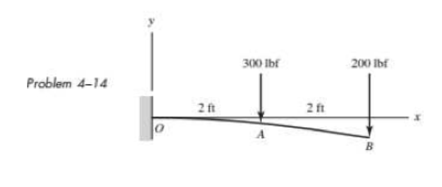
Chapter 4, Problem 14P
An aluminum tube with outside diameter of 2 in and inside diameter of 1.5 in is cantilevered and loaded as shown. Using the formulas in Appendix Table A–9 and superposition, find the deflection at B.
Expert Solution & Answer
Want to see the full answer?
Check out a sample textbook solution
Students have asked these similar questions
the theoritcal part. consider the load N as 495 Newtons. take a 15 only for cross section. find the deflection for it analytically.
A gear reduction unit uses the countershaft shown in the figure. Gear A receives power from another gear with the transmitted force
FA applied at the 20° pressure angle as shown. The power is transmitted through the shaft and delivered through gear B through a
transmitted force Fg at the pressure angle shown. For the steel countershaft specified in the table, find the deflection and slope of the
shaft at point A. Use superposition with the deflection equations in Table A-9. Assume the bearings constitute simple supports. In the
figure below, FA is 11400 N and the diameter of the shaft (dshaft) is 52 mm.
20⁰
400 mm
Gear A, 600-mm dia.
350 mm
300 mm
Gear B, 300-mm dia.
The deflection at point A is
The slope at point A is 0.0041 rad.
2.2 mm.
25°
✓
dshaft
On a formatted bond paper, copy and solve
the problem. Show your neat and detailed
solution. Use three (3) decimal places for
your answers and enclosed it in a box.
Compute the deflection and slope at a
section 8 ft from the wall for the beam shown
in the figure using Double Integration Method.
Assume that E = 28 x 103 psi and 1= 30.75
1200 lb
in4.
A
800 lb/ft
-8 ft
-8 ft
B
Chapter 4 Solutions
Shigley's Mechanical Engineering Design (McGraw-Hill Series in Mechanical Engineering)
Ch. 4 - The figure shows a torsion bar OA fixed at O,...Ch. 4 - For Prob. 41, if the simple support at point A...Ch. 4 - A torsion-bar spring consists of a prismatic bar,...Ch. 4 - An engineer is forced by geometric considerations...Ch. 4 - A bar in tension has a circular cross section and...Ch. 4 - Prob. 6PCh. 4 - Prob. 7PCh. 4 - Derive the equations given for beam 2 in Table A9...Ch. 4 - Derive the equations given for beam 5 in Table A9...Ch. 4 - The figure shows a cantilever consisting of steel...
Ch. 4 - A simply supported beam loaded by two forces is...Ch. 4 - Using superposition, find the deflection of the...Ch. 4 - A rectangular steel bar supports the two...Ch. 4 - An aluminum tube with outside diameter of 2 in and...Ch. 4 - The cantilever shown in the figure consists of two...Ch. 4 - Using superposition for the bar shown, determine...Ch. 4 - A simply supported beam has a concentrated moment...Ch. 4 - Prob. 18PCh. 4 - Using the results of Prob. 418, use superposition...Ch. 4 - Prob. 20PCh. 4 - Consider the uniformly loaded simply supported...Ch. 4 - Prob. 22PCh. 4 - Prob. 23PCh. 4 - Prob. 24PCh. 4 - Prob. 25PCh. 4 - Prob. 26PCh. 4 - Prob. 27PCh. 4 - Prob. 28PCh. 4 - 429 to 434 For the steel countershaft specified in...Ch. 4 - Prob. 30PCh. 4 - Prob. 31PCh. 4 - Prob. 32PCh. 4 - For the steel countershaft specified in the table,...Ch. 4 - For the steel countershaft specified in the table,...Ch. 4 - Prob. 35PCh. 4 - Prob. 36PCh. 4 - Prob. 37PCh. 4 - Prob. 38PCh. 4 - Prob. 39PCh. 4 - Prob. 40PCh. 4 - The cantilevered handle in the figure is made from...Ch. 4 - Prob. 42PCh. 4 - The cantilevered handle in Prob. 384, p. 154, is...Ch. 4 - A flat-bed trailer is to be designed with a...Ch. 4 - The designer of a shaft usually has a slope...Ch. 4 - Prob. 46PCh. 4 - If the diameter of the steel beam shown is 1.25...Ch. 4 - For the beam of Prob. 4-47, plot the magnitude of...Ch. 4 - Prob. 49PCh. 4 - 4-50 and 4-51 The figure shows a rectangular...Ch. 4 - and 451 the ground at one end and supported by a...Ch. 4 - The figure illustrates a stepped torsion-bar...Ch. 4 - Consider the simply supported beam 5 with a center...Ch. 4 - Prob. 54PCh. 4 - Prob. 55PCh. 4 - Solve Prob. 410 using singularity functions. Use...Ch. 4 - Prob. 57PCh. 4 - Prob. 58PCh. 4 - Prob. 59PCh. 4 - Solve Prob. 413 using singularity functions. Since...Ch. 4 - Prob. 61PCh. 4 - Solve Prob. 419 using singularity functions to...Ch. 4 - Using singularity functions, write the deflection...Ch. 4 - Determine the deflection equation for the...Ch. 4 - Use Castiglianos theorem to verify the maximum...Ch. 4 - Use Castiglianos theorem to verify the maximum...Ch. 4 - Solve Prob. 415 using Castiglianos theorem.Ch. 4 - Solve Prob. 452 using Castiglianos theoremCh. 4 - Determine the deflection at midspan for the beam...Ch. 4 - Using Castiglianos theorem, determine the...Ch. 4 - Solve Prob. 441 using Castiglianos theorem. Since...Ch. 4 - Solve Prob. 442 using Castiglianos theorem.Ch. 4 - The cantilevered handle in Prob. 384 is made from...Ch. 4 - Solve Prob. 450 using Castiglianos theorem.Ch. 4 - Solve Prob. 451 using Castiglianos theorem.Ch. 4 - The steel curved bar shown has a rectangular cross...Ch. 4 - Repeat Prob. 476 to find the vertical deflection...Ch. 4 - For the curved steel beam shown. F = 6.7 kips....Ch. 4 - A steel piston ring has a mean diameter of 70 mm....Ch. 4 - For the steel wire form shown, use Castiglianos...Ch. 4 - 4-81 and 4-82 The part shown is formed from a...Ch. 4 - 4-81 and 4-82 The part shown is formed from a...Ch. 4 - Repeat Prob. 481 for the vertical deflection at...Ch. 4 - Repeat Prob. 482 for the vertical deflection at...Ch. 4 - A hook is formed from a 2-mm-diameter steel wire...Ch. 4 - The figure shows a rectangular member OB, made...Ch. 4 - Prob. 87PCh. 4 - For the wire form shown, determine the deflection...Ch. 4 - Prob. 89PCh. 4 - Prob. 90PCh. 4 - Prob. 91PCh. 4 - Prob. 92PCh. 4 - Solve Prob. 492 using Castiglianos method and...Ch. 4 - An aluminum step bar is loaded as shown. (a)...Ch. 4 - The steel shaft shown in the figure is subjected...Ch. 4 - Repeat Prob. 495 with the diameters of section OA...Ch. 4 - The figure shows a 12- by 1-in rectangular steel...Ch. 4 - For the beam shown, determine the support...Ch. 4 - Solve Prob. 498 using Castiglianos theorem and...Ch. 4 - Consider beam 13 in Table A9, but with flexible...Ch. 4 - Prob. 101PCh. 4 - The steel beam ABCD shown is simply supported at C...Ch. 4 - Prob. 103PCh. 4 - A round tubular column has outside and inside...Ch. 4 - For the conditions of Prob. 4104, show that...Ch. 4 - Link 2, shown in the figure, is 25 mm wide, has...Ch. 4 - Link 3, shown schematically in the figure, acts as...Ch. 4 - The hydraulic cylinder shown in the figure has a...Ch. 4 - The figure shows a schematic drawing of a...Ch. 4 - If drawn, a figure for this problem would resemble...Ch. 4 - Design link CD of the hand-operated toggle press...Ch. 4 - Find the maximum values of the spring force and...Ch. 4 - As shown in the figure, the weight W1 strikes W2...Ch. 4 - Part a of the figure shows a weight W mounted...
Knowledge Booster


Learn more about
Need a deep-dive on the concept behind this application? Look no further. Learn more about this topic, mechanical-engineering and related others by exploring similar questions and additional content below.Similar questions
- Problem 9 only, solve carefully, include the units in every step and draw the diagram. Thanks! A force tangent to 1 foot diameter pulley is 5 KN and is mounted on a 2 inches shaft. Determine the torsional deflectionif G = 83 x 106 Kpaarrow_forwardThe given figures shows a cantilever of spa L subjected to a concentrated load Pand moment Mat the free end. Deflection at th free end is given by 7. M.arrow_forwardThe deflection at point b=-.0273in, the deflection at point c= -.117in. Please show how to get there.arrow_forward
- A rectangular steel bar supports the two overhanging loads. Using superposition, find the deflection at the ends and at the center.arrow_forwardes A gear reduction unit uses the countershaft shown in the figure. Gear A receives power from another gear with the transmitted force FA applied at the 20° pressure angle as shown. The power is transmitted through the shaft and delivered through gear B through a transmitted force Fg at the pressure angle shown. For the steel countershaft specified in the table, find the deflection and slope of the shaft at point A. Use superposition with the deflection equations in Table A-9. Assume the bearings constitute simple supports. In the figure below, FA is 310 lbf and the diameter of the shaft (dshaft) is 1.29 in. dshaft Gear A 20-in dia. 16 in FA 20⁰ The deflection at point A is The slope at point A is 14 in 100 Gear B 8-in dia. rad. 9 in in. B FB 20°arrow_forwardFor the wire form shown, use Castigliano's method to determine the deflec- tion of point A in the y direction. Consider the effects of bending and torsion only. Use the straight beam formulation for the bending energy. The wire is steel with E 200 GPa, v = 0.29, and has a diameter of 5 mm. Before cation of the 200-N force the wire form is in the xz plane 100 mm. = appli- where the radius R isarrow_forward
- The beam is supported by a pin at point A and a roller at point C. A distributed load is applied to the beam. Neglect the weight and thickness of the beam. Hints: 1. will need to use similar triangles to find the height after sectioning at B. 2. Review direction of normal force, shear force and bending moment and which is positive or negative. W2 W1 A di d2 Values for the figure are given in the following table. Note the figure may not be to scale. Variable Value W1 190 N-m W2 440 N-m di 5 m d2 5 m a. Determine the magnitude of the normal force at point B, NB. . b. Determine the magnitude of the shear force at point B, VB- c. Is the shear force VB a positive or negative shear force? d. Determine the magnitude of the bending moment at point B, MB. e. Is the bending moment MB a positive or negative bending moment? Round your final answers to 3 significant digits/figures.arrow_forwardThe figure shows a cantilever consisting of steel angles size 100 x 100 x 12 mm mounted back to back. Using superposition, find the deflection at B and the maximum stress in the beam. 3 m 2.5 kN - 2 m I kN/m explain every step and define every equation. neat writing.arrow_forwardFor the vertical rod as shown, find the deflection at A and the stress distribution. Use E-100 MPa and weight per unit volume equal to 0.06 N/cm3. (Hint: Introduce weight contribution to the nodal loads and solve using two elements and four elements.) Comment on the stress distribution. a) Use 2 & 4 elements with linear shape functions. b) Use 2 elements with quadratic shape functions. 1.6m C A -Area - 2500 cm² 8 Area - 1500 cm²arrow_forward
- A uniform bar is simply supported at the ends, carries a concentrated load P at the mid span. If the same load be alternatively, uniformly distributed over the full length of the bar. What will be the decrease in maximum deflection of the bar.arrow_forward-3 The deflection curve for a simple beam AB (see figure) is given by v=q0x360LEI(7L410L2x2+3x4) Describe the load acting on the beam.arrow_forwardPlot the load-deflection diagram for a pinned-end column with eccentric axial loads (see figure) if the eccentricity e of the load is 5 mm and the column has a length L = 3.6 m, moment of inertia L = 9,0 × 106 mm4, and modulus of elasticity E = 210 GPa. Note: Plot the axial load as ordinate and the deflection at the midpoint as abscissa.arrow_forward
arrow_back_ios
SEE MORE QUESTIONS
arrow_forward_ios
Recommended textbooks for you
 Mechanics of Materials (MindTap Course List)Mechanical EngineeringISBN:9781337093347Author:Barry J. Goodno, James M. GerePublisher:Cengage Learning
Mechanics of Materials (MindTap Course List)
Mechanical Engineering
ISBN:9781337093347
Author:Barry J. Goodno, James M. Gere
Publisher:Cengage Learning
Solids: Lesson 53 - Slope and Deflection of Beams Intro; Author: Jeff Hanson;https://www.youtube.com/watch?v=I7lTq68JRmY;License: Standard YouTube License, CC-BY