
Shigley's Mechanical Engineering Design (McGraw-Hill Series in Mechanical Engineering)
10th Edition
ISBN: 9780073398204
Author: Richard G Budynas, Keith J Nisbett
Publisher: McGraw-Hill Education
expand_more
expand_more
format_list_bulleted
Concept explainers
Videos
Textbook Question
Chapter 4, Problem 51P
and
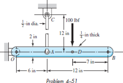
4–51 the ground at one end and supported by a 12 -in-diameter round steel rod with hooks formed on the ends. A load of 100 lbf is applied as shown. Use superposition to determine the vertical deflection
at point B.
4–51
Expert Solution & Answer
Want to see the full answer?
Check out a sample textbook solution
Students have asked these similar questions
The simply supported beam is subjected to the loads as described in the figure and parameter table.
Neglecting the thickness of the beam, calculate the horizontal and vertical support reactions at A and B.
F
A
B
C
-4*-
L3
parameter
value
units
L1
L2
L3
ft
4
ft
6
ft
theta
65
F
200
lb
M
500
lb-ft
For the answers, take to the right and up to be the positive directions.
The support reaction at A in the z direction is NAz-
lb
The support reaction at A in the y direction is NAy-
lb
The support reaction at Bin the z direction is NB=
lb
The support reaction at Bin the y direction is NBy=
lb
Problem Statement
Based on Problem 5-22 from the textbook.
if the intensity of the distributed load acting
on the beam is w, determine the reactions at
the roller A and pin B. W=2.6 kN/m
a=2.4 m
b=4.8 m
Theta 25 degrees
A
W
ming
B
Determine the reaction components at the roller support at B and the hinge
support at C due to the applied load shown in this figure.
10 kips
4
-3 ft-
Support at B,
Rg = 6 kips vertically upward direction.
Support at C,
Re-25 kips makes an angle 0= -33.13° with respect to +X axis.
mm B
Support at C,
Rc-20 kips makes an angle 0-43.13 with respect to + X axis.
Support at B,
Rg - 36 kips vertically downward direction.
Support at C,
Re 15 kips makes an angle 0- 63.13 with respect to + X axis.
Support at B,
-3 ft-
Chapter 4 Solutions
Shigley's Mechanical Engineering Design (McGraw-Hill Series in Mechanical Engineering)
Ch. 4 - The figure shows a torsion bar OA fixed at O,...Ch. 4 - For Prob. 41, if the simple support at point A...Ch. 4 - A torsion-bar spring consists of a prismatic bar,...Ch. 4 - An engineer is forced by geometric considerations...Ch. 4 - A bar in tension has a circular cross section and...Ch. 4 - Prob. 6PCh. 4 - Prob. 7PCh. 4 - Derive the equations given for beam 2 in Table A9...Ch. 4 - Derive the equations given for beam 5 in Table A9...Ch. 4 - The figure shows a cantilever consisting of steel...
Ch. 4 - A simply supported beam loaded by two forces is...Ch. 4 - Using superposition, find the deflection of the...Ch. 4 - A rectangular steel bar supports the two...Ch. 4 - An aluminum tube with outside diameter of 2 in and...Ch. 4 - The cantilever shown in the figure consists of two...Ch. 4 - Using superposition for the bar shown, determine...Ch. 4 - A simply supported beam has a concentrated moment...Ch. 4 - Prob. 18PCh. 4 - Using the results of Prob. 418, use superposition...Ch. 4 - Prob. 20PCh. 4 - Consider the uniformly loaded simply supported...Ch. 4 - Prob. 22PCh. 4 - Prob. 23PCh. 4 - Prob. 24PCh. 4 - Prob. 25PCh. 4 - Prob. 26PCh. 4 - Prob. 27PCh. 4 - Prob. 28PCh. 4 - 429 to 434 For the steel countershaft specified in...Ch. 4 - Prob. 30PCh. 4 - Prob. 31PCh. 4 - Prob. 32PCh. 4 - For the steel countershaft specified in the table,...Ch. 4 - For the steel countershaft specified in the table,...Ch. 4 - Prob. 35PCh. 4 - Prob. 36PCh. 4 - Prob. 37PCh. 4 - Prob. 38PCh. 4 - Prob. 39PCh. 4 - Prob. 40PCh. 4 - The cantilevered handle in the figure is made from...Ch. 4 - Prob. 42PCh. 4 - The cantilevered handle in Prob. 384, p. 154, is...Ch. 4 - A flat-bed trailer is to be designed with a...Ch. 4 - The designer of a shaft usually has a slope...Ch. 4 - Prob. 46PCh. 4 - If the diameter of the steel beam shown is 1.25...Ch. 4 - For the beam of Prob. 4-47, plot the magnitude of...Ch. 4 - Prob. 49PCh. 4 - 4-50 and 4-51 The figure shows a rectangular...Ch. 4 - and 451 the ground at one end and supported by a...Ch. 4 - The figure illustrates a stepped torsion-bar...Ch. 4 - Consider the simply supported beam 5 with a center...Ch. 4 - Prob. 54PCh. 4 - Prob. 55PCh. 4 - Solve Prob. 410 using singularity functions. Use...Ch. 4 - Prob. 57PCh. 4 - Prob. 58PCh. 4 - Prob. 59PCh. 4 - Solve Prob. 413 using singularity functions. Since...Ch. 4 - Prob. 61PCh. 4 - Solve Prob. 419 using singularity functions to...Ch. 4 - Using singularity functions, write the deflection...Ch. 4 - Determine the deflection equation for the...Ch. 4 - Use Castiglianos theorem to verify the maximum...Ch. 4 - Use Castiglianos theorem to verify the maximum...Ch. 4 - Solve Prob. 415 using Castiglianos theorem.Ch. 4 - Solve Prob. 452 using Castiglianos theoremCh. 4 - Determine the deflection at midspan for the beam...Ch. 4 - Using Castiglianos theorem, determine the...Ch. 4 - Solve Prob. 441 using Castiglianos theorem. Since...Ch. 4 - Solve Prob. 442 using Castiglianos theorem.Ch. 4 - The cantilevered handle in Prob. 384 is made from...Ch. 4 - Solve Prob. 450 using Castiglianos theorem.Ch. 4 - Solve Prob. 451 using Castiglianos theorem.Ch. 4 - The steel curved bar shown has a rectangular cross...Ch. 4 - Repeat Prob. 476 to find the vertical deflection...Ch. 4 - For the curved steel beam shown. F = 6.7 kips....Ch. 4 - A steel piston ring has a mean diameter of 70 mm....Ch. 4 - For the steel wire form shown, use Castiglianos...Ch. 4 - 4-81 and 4-82 The part shown is formed from a...Ch. 4 - 4-81 and 4-82 The part shown is formed from a...Ch. 4 - Repeat Prob. 481 for the vertical deflection at...Ch. 4 - Repeat Prob. 482 for the vertical deflection at...Ch. 4 - A hook is formed from a 2-mm-diameter steel wire...Ch. 4 - The figure shows a rectangular member OB, made...Ch. 4 - Prob. 87PCh. 4 - For the wire form shown, determine the deflection...Ch. 4 - Prob. 89PCh. 4 - Prob. 90PCh. 4 - Prob. 91PCh. 4 - Prob. 92PCh. 4 - Solve Prob. 492 using Castiglianos method and...Ch. 4 - An aluminum step bar is loaded as shown. (a)...Ch. 4 - The steel shaft shown in the figure is subjected...Ch. 4 - Repeat Prob. 495 with the diameters of section OA...Ch. 4 - The figure shows a 12- by 1-in rectangular steel...Ch. 4 - For the beam shown, determine the support...Ch. 4 - Solve Prob. 498 using Castiglianos theorem and...Ch. 4 - Consider beam 13 in Table A9, but with flexible...Ch. 4 - Prob. 101PCh. 4 - The steel beam ABCD shown is simply supported at C...Ch. 4 - Prob. 103PCh. 4 - A round tubular column has outside and inside...Ch. 4 - For the conditions of Prob. 4104, show that...Ch. 4 - Link 2, shown in the figure, is 25 mm wide, has...Ch. 4 - Link 3, shown schematically in the figure, acts as...Ch. 4 - The hydraulic cylinder shown in the figure has a...Ch. 4 - The figure shows a schematic drawing of a...Ch. 4 - If drawn, a figure for this problem would resemble...Ch. 4 - Design link CD of the hand-operated toggle press...Ch. 4 - Find the maximum values of the spring force and...Ch. 4 - As shown in the figure, the weight W1 strikes W2...Ch. 4 - Part a of the figure shows a weight W mounted...
Knowledge Booster


Learn more about
Need a deep-dive on the concept behind this application? Look no further. Learn more about this topic, mechanical-engineering and related others by exploring similar questions and additional content below.Similar questions
- Figure 4-26/27 Full Alternative Text *4-28. The rod has a slight taper and length L. It is suspended from the ceiling and supports a load P at its end. Show that the displacement of its end due to this load is 8 = PL/(TET ₂1). Neglect the weight of the material. The modulus of elasticity is E. Prob. 4-28 12. 11 P Larrow_forwardA beam AB is 14 m long weighs 15 N resting on the two supports at the end. If the beam carries loads at the positions shown in the figure, what are the reactive forces at the supports A & B? Neglect the self-weight of the beam. Take F, = 9 N, F2 = 14 N, O = 25° and AC = BD = 3.5 m. -- F1 F2 D A (NOTE: ENTER ONLY THE VALUES BY REFERRING TO THE UNITS GIVEN IN THE BRACKET. ALSO, SUBMIT THE HANDWRITTEN ANSWER SHEET IN THE LINK PROVIDED) The reaction at the support 'A' = RA (in N) =arrow_forwardA beam AB is 14 m long weighs 15 N resting on the two supports at the end. If the beam carries loads at the positions shown in the figure, what are the reactive forces at the supports A & B? Neglect the self-weight of the beam. Take F, = 9 N, F2 = 14 N, O = 25° and AC = BD = 3.5 m. -- F1 F2 D A (NOTE: ENTER ONLY THE VALUES BY REFERRING TO THE UNITS GIVEN IN THE BRACKET. ALSO, SUBMIT THE HANDWRITTEN ANSWER SHEET IN THE LINK PROVIDED) The reaction at the support 'A' = RA (in N) = The reaction at the support 'B' = Rg (in N) =arrow_forward
- Problem Statement Based on Problem 5-11 from the textbook. Determine the reactions at the supports. W=3.9kN/m a=2.3m b=5.0m Theta 30 degrees a W Barrow_forwardA beam AB is 13 m long weighs 10 N resting on the two supports at the end. If the beam carries loads at the positions shown in the figure, what are the reactive forces at the supports A & B? Neglect the self-weight of the beam. Take F, = 6 N, F2 = 11 N, e = 25° and AC = BD = 3.25 m. -- F1 F2 e A B (NOTE: ENTER ONLY THE VALUES BY REFERRING TO THE UNITS GIVEN IN THE BRACKET. ALSO, SUBMIT THE HANDWRITTEN ANSWER SHEET IN THE LINK PROVIDED) The reaction at the support 'A' = RA (in N) = The reaction at the support 'B' = Rg (in N) =arrow_forward4. A homogeneous rod of constant cross section is attached to unyielding supports. It carries an axial load P applied as shown in the figure. Prove that the reactions are given by R1 = Pb/L and R2 = Pa/L. (Note that these reactions are equivalent to those of a simply supported beam carrying a concentrated load). R1 P R2 -a b Larrow_forward
- The rigid arm AB is attached to the end of the solid circular steel rod BC. The rod is supported by bearings at B and a fixed support at C. The bearings at B prevent rod BC from translating up, down, left, or right, but the bearings do allow rod BC to rotate freely about the x axis at B. It is required that the vertical deflection of point A not exceed 0.25 in. when a load of P = 700 lb is applied at A. Determine the minimum diameter needed for rod BC. Use a = 18 in. and b = 45 in. The modulus of rigidity of the rod is G = 11×106 psi. A P Answer: dmin = i a B b in. Carrow_forwardThe three concentrated load is supported by a T beam shown in figure. Determine the maximum value of P so that Gensile ≤ 12 ksi and compressive ≤20 ksi. 2in K 3P 4ft 7ft R₁ 7ft 4ft R₂ k4in 8in 2inarrow_forwardTwo steel shafts (G = 77.2 GPa) are connected to a coupling disk B and to fixed supports at A and C. Shaft BC is solid, while shaft AB is hollow with an inner diameter of 25 mm. Take T = 1.1 kN·m. Calculate the reaction at support A and Carrow_forward
- The steel box wrench (E=29,000ksi, v=0.32) is loaded with a 40-lb horizontal force and a 25-lb vertical force. Find the following for an element located at point B on Section a-a: 24 in. 1. The non-vanishing resultant internal moments on section a-a are which of the following? 4 in. a. (160 i- 600 j+960 k)in · Ib b. (-160 i+600 j+960 k ) in · lb c. (-960 i+160 j+600 k)in - lb d. (-960 i -160 ј-600 k)in-lb a e. none of the above 2. The normal and shear force components on section a-a are: a. V, = 65lb;V, = 40lb; N¸ = 25lb b. V, = 0;V, =40lb; N, = 25lb c. V, = 64;V, = 25lb; N, = 40lb d. V, =0;V, =-40lb; N¸ = -25lb e. none of the above 3. The non-vanishing stress components at point B are: 0̟ =1.60; t =-4.89ksi; а. 0, =-4.89; 7 =3.60ksi; 0, = 2.50ksi; T, d. o, = 4.91ksi; t =-4.89ksi; b. с. =-4.89ksi; е. none of the above 4. The principal stresses at point B from most tensile to most compressive are: O1,02,0; =4.16,–0.8,–5.76 b. o,,0,,0, =5.76,0,–4.16 а. O1,02,0; =1.9,-2.45,-6.8 с. d.…arrow_forwardThe compound beam shown in (Eigure 1) is fixed at E and supported by a rocker at A and B. There are hinges (pins) at C and D. The 4-kN load is applied just to the right of the pin at D. Suppose that w = 5 kN/m. Figure 4 kN 6kN I. conf 1 of 1 -2m-2m-2m-3m- 3m ▼ Determine the y component of reaction at A. Express your answer to three significant figures and include the appropriate units. A₁ = Value Submit Part B B, = HA Submit Part C Request Answer Determine the y component of reaction at B. Express your answer to three significant figures and include the appropriate units. Value KN Request Answer ? KN ? Determine the component of reaction at E.. Express your answer to three significant figures and include the appropriate units.arrow_forward2-12. For the truss shown in the figure, deter- mine the total elongation of the member BC due to the application of the force P = 450 kN. The || member BC is made from steel and is 60 mm² in cross-sectional area. E = 210 000 MN/m². %3| B 1.20 m D 450 kN 5 spaces at 0.90 m = 4.50 m %3Darrow_forward
arrow_back_ios
SEE MORE QUESTIONS
arrow_forward_ios
Recommended textbooks for you
 Mechanics of Materials (MindTap Course List)Mechanical EngineeringISBN:9781337093347Author:Barry J. Goodno, James M. GerePublisher:Cengage Learning
Mechanics of Materials (MindTap Course List)
Mechanical Engineering
ISBN:9781337093347
Author:Barry J. Goodno, James M. Gere
Publisher:Cengage Learning
Column buckling; Author: Amber Book;https://www.youtube.com/watch?v=AvvaCi_Nn94;License: Standard Youtube License