
Mechanics of Materials (MindTap Course List)
9th Edition
ISBN: 9781337093347
Author: Barry J. Goodno, James M. Gere
Publisher: Cengage Learning
expand_more
expand_more
format_list_bulleted
Concept explainers
Videos
Textbook Question
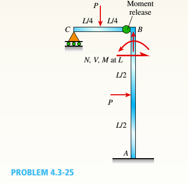
Chapter 4, Problem 4.3.25P
Frame ABC has a moment release just left of joint B. Find axial force N, shear force V, and moment M at the top of column AB. Write variables N, V, and M in terms of variables P and L.
Expert Solution & Answer

Trending nowThis is a popular solution!

Students have asked these similar questions
estion 12
Find the moment about B and D for the loaded section as shown in figure. The forces F1 =10 N, F2 = 50 N, F3 = 28N, F4 =30 N. AB =14 m, BC=10m, CD = 9 m, 0, =45°.
ot yet
nswered
(ENTER ONLY THE VALUES BY REFERRING THE UNITS GIVEN I
| BRACKET. ALSO SUBMIT THE HAND WRITTEN ANSWER SHEET IN THE LINK PROVIDED)
arked out of
00
F3
Flag
Jestion
F4
D
F2
O The moment about 'B' (in Nm) =
(i) The moment about D' (in Nm) =
Consider the following FBD of bar ABC with the pulleys included
Write the moment equation M max /A,Z = 0 interms of the forces Ax , Ay ,T and TBD Use the dimensions given in the figure Note that the radius of the pulleys is set given. Show that the radius is not needed
if you can explain clearly
The light boom AB is attached to a vertical wall by a ball and socket joint at A and supported by two cables at B. A force P is applied at B where P = 16i - 13j kN.Note that the reaction force at A acts along the boom because it is a two-force member. Calculate the magnitude of the reaction force at A in kN.
Determine the magnitude of the moment of P about the y-axis in Nm.
Determine the magnitude of the moment of P about the z-axis in Nm.
Determine the magnitude of the moment of P about the origin (point O) in Nm.
Chapter 4 Solutions
Mechanics of Materials (MindTap Course List)
Ch. 4 - Calculate the shear force V and bending moment...Ch. 4 - Determine the shear force V and bending moment M...Ch. 4 - Determine the shear force V and bending moment M...Ch. 4 - Calculate the shear force V and bending moment M...Ch. 4 - Consider the beam with an overhang shown in the...Ch. 4 - The beam ABC shown in the figure is simply...Ch. 4 - The beam ABCD shown in the figure has overhangs at...Ch. 4 - At a full d raw, an archer applies a pull of 130 N...Ch. 4 - A curved bar ABC is subjected to loads in the form...Ch. 4 - Under cruising conditions, the distributed load...
Ch. 4 - A beam ABCD with a vertical arm CE is supported as...Ch. 4 - A simply supported beam AB supports a trapezoid...Ch. 4 - Beam ABCD represents a reinforced-concrete...Ch. 4 - Find shear (V) and moment (M) at x = 3L/4 for the...Ch. 4 - Find expressions for shear force V and moment M at...Ch. 4 - Find expressions for shear force V and moment Mat...Ch. 4 - Find expressions for shear force V and moment Mat...Ch. 4 - Find expressions for shear force V and moment M at...Ch. 4 - Find expressions for shear force V and moment M at...Ch. 4 - Find expressions for shear force V and moment M at...Ch. 4 - A cable with force P is attached to a frame at A...Ch. 4 - Find expressions for shear force V and moment M at...Ch. 4 - A cable with force P is attached to a frame at D...Ch. 4 - Frame ABCD carries two concentrated loads (2P at T...Ch. 4 - Frame ABC has a moment release just left of joint...Ch. 4 - The simply supported beam ABCD is loaded by a...Ch. 4 - The centrifuge shown in the figure rotates in a...Ch. 4 - Draw the shear-Force and bending-moment diagrams...Ch. 4 - A simple beam AB is subjected to a counter...Ch. 4 - Draw the shear-force and bending-moment diagrams...Ch. 4 - The cantilever beam AB shown in the figure is...Ch. 4 - Cantilever beam AB carries an upward uniform load...Ch. 4 - The simple beam AB shown in the figure is...Ch. 4 - A simple beam AB subjected to couples M1and 3M2...Ch. 4 - A simply supported beam ABC is loaded by a...Ch. 4 - A simply supported beam ABC is loaded at the end...Ch. 4 - A beam ABC is simply supported at A and B and has...Ch. 4 - Beam ABCD is simply supported at B and C and has...Ch. 4 - Draw the shear-force and bending-moment diagrams...Ch. 4 - The simple beam AB supports a triangular load of...Ch. 4 - The beam AB shown in the figure supports a uniform...Ch. 4 - A cantilever beam AB supports a couple and a...Ch. 4 - The cantilever beam A B shown in the figure is...Ch. 4 - Beam ABC has simple supports at .A and B. an...Ch. 4 - Beam ABC with an overhang at one end supports a...Ch. 4 - Consider the two beams shown in the figures. Which...Ch. 4 - The three beams in the figure have the same...Ch. 4 - The beam ABC shown in the figure is simply...Ch. 4 - A simple beam AB is loaded by two segments of...Ch. 4 - Two beams (see figure) are loaded the same and...Ch. 4 - The beam A BCD shown in the figure has overhangs...Ch. 4 - A beam ABCD with a vertical arm CE is supported as...Ch. 4 - Beams ABC and CD are supported at A,C, and D and...Ch. 4 - The simple beam ACE shown in the figure is...Ch. 4 - A beam with simple supports is subjected to a...Ch. 4 - A beam of length L is designed to support a...Ch. 4 - The compound beam ABCDE shown in the figure...Ch. 4 - Draw the shear-force and bending-moment diagrams...Ch. 4 - The shear-force diagram for a simple beam is shown...Ch. 4 - The shear-force diagram for a beam is shown in the...Ch. 4 - A compound beam (see figure) has an internal...Ch. 4 - A compound beam (see figure) has an shear release...Ch. 4 - A simple beam AB supports two connected wheel...Ch. 4 - The inclined beam represents a ladder with the...Ch. 4 - Beam ABC is supported by a tie rod CD as shown....Ch. 4 - A plane frame (see figure) consists of column AB...Ch. 4 - The plane frame shown in the figure is part of an...
Knowledge Booster


Learn more about
Need a deep-dive on the concept behind this application? Look no further. Learn more about this topic, mechanical-engineering and related others by exploring similar questions and additional content below.Similar questions
- A simply supported beam ABC is loaded at the end of a bracket BDE (see figure). Draw axial-force, shear-force, and bending-moment diagrams for ABC.arrow_forwardA force F = 1757 N acts upon a piston head, as shown in the figure. The gudgeon pin G connects the connecting rod to pin C where it connects to the crankshaft at S in a large military vehicle. Find the moment of the force at S.arrow_forwardabout the point (0). moments of these forces АВСD as 6N 3m 5m B 250 N 15% 1- Calculate the moment of the (300 N ) force on the handle of the monkey wrench about 200 mm 30 mm the center of the bolt . T00 mm hout point O.arrow_forward
- In the crane shown, assume that the horizontal arm of the crane weighs 200 kg/m. If a counterweight of 100kN is used, what is the capacity P of the crane? Also find the moment at the base of the crane when no load is being carried (i.e., when P=0). What weight should be added so that the capacity would rise to 8 tons? 130 On-arrow_forward3 moment equation for this problemarrow_forwardPROBLEM 3: A right-angled rigid pipe is fixed to a wall at A and is additionally supported through the cable CD as shown in the figure. The tension in the cable is 3 kN. Neglect the weight of the pipe. Use the Right-Hand-Rule to indicate the direction of the moment. [8] Calculate total force reaction at A. (ANSWER: 3.00 KN) [9] Calculate the moment reaction (including correct sign) at A about z-axis. (ANSWER: 2.168 KN-m) [10] Calculate the moment reaction (including correct sign) at A about x-axis. (ANSWER: -0.843 KN-m)arrow_forward
- Find the moment of the forces shown in fig w.r.t. point A? If P= 250 N Q= 150 N y 0.2 m A P 350 -0.18 m- -0.12 m-arrow_forwardAssignment: In the figure, the boom AC is acted upon by a vertical load W = 600lbs, a forceT= 440 lbs directed from B to D, and a force P = 280lbs directed from A to E. Find the force F to be applied at C to reduce the resultant on the boom to a couple. What is this couple? 12'1 W. Figure P-2-13.23arrow_forwardA member is loaded with force system as shown in figure. Find the Moment about A, B, C, D andE Where F1= 80 N, F2 =45 N, F3 =10 N, F4 =30 N, Fs =45 N, AB =80 m, Point C is in the mid of AE, CD = 35m, AE =120 m. the angle e =45° (5 marks) (Enter only the values in the boxes provided) F4 Fs F1 D F F: OThe moment about the point 'A' (unit in Nm), MA = (i) The moment about the point 'B' (unit in Nm) „Mg = (ii) The moment about the point 'C (unit in Nm). Mc = (iv) The moment about the point 'D' (unit in Nm), Mp = (v) The moment about the point 'E'(unit in Nm), MẸ =arrow_forward
- The inclined beam represents a ladder with the Following applied loads: the weight (W) of the house painter and the distributed weight (u) of the ladder itself. Find support reactions at A and B: then plot axial force (N), shear (V), and moment (M) diagrams. Label all critical N, V, and M values and also the distance to points where any critical ordmates are zero. Plot N, V, and M diagrams normal to the inclined ladder. Repeat part (a) for the case of the ladder suspended from a pin at B and traveling on a roller support perpendicular to the floor at A.arrow_forwardThe three beams in the figure have the same loading. However, one has a moment release just to the left of C, the second has a shear release just to the right of C, and the third has an axial release just to the left of C. Which beam has the largest maximum moment? First, find support reactions; then plot axial force (N), shear ( V) and moment (M) diagrams for all three beams. Label all critical N, K, and M values and also the distance to points where N, K and loi M are zero.arrow_forwardBeam ABC is supported by a tie rod CD as shown. Two configurations are possible: pin support at A and downward triangular load on AB or pin at B and upward load on AB. Which has the larger maximum moment? First, find all support reactions; then plot axial force (N), shear (V), and moment (M) diagrams for ABC only and label all critical N, V, and M values. Label the distance to points where any critical ordinates are zero.arrow_forward
arrow_back_ios
SEE MORE QUESTIONS
arrow_forward_ios
Recommended textbooks for you
 Mechanics of Materials (MindTap Course List)Mechanical EngineeringISBN:9781337093347Author:Barry J. Goodno, James M. GerePublisher:Cengage Learning
Mechanics of Materials (MindTap Course List)
Mechanical Engineering
ISBN:9781337093347
Author:Barry J. Goodno, James M. Gere
Publisher:Cengage Learning
EVERYTHING on Axial Loading Normal Stress in 10 MINUTES - Mechanics of Materials; Author: Less Boring Lectures;https://www.youtube.com/watch?v=jQ-fNqZWrNg;License: Standard YouTube License, CC-BY