
Mechanics of Materials (MindTap Course List)
9th Edition
ISBN: 9781337093347
Author: Barry J. Goodno, James M. Gere
Publisher: Cengage Learning
expand_more
expand_more
format_list_bulleted
Concept explainers
Videos
Textbook Question
Chapter 4, Problem 4.3.8P
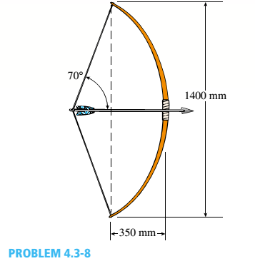
At a full d raw, an archer applies a pull of 130 N to the bowstring of the bow shown in the figure. Determine the bending moment at the midpoint of the bow.
Expert Solution & Answer

Trending nowThis is a popular solution!

Students have asked these similar questions
Determine the shear force equation on segment AB in Ib
Determine the bending moment equation on segment AB in Ib-ft.
Determine the shear force equation on segment BC in Ib.
Determine the bending moment equation on segment BC in Ib-ft.
Determine the point of zero shear from point A in feet.
Determine the bending moment at the point of zero shear in Ib-ft.
At a full draw, an archer applies a pull of 130 Nto the bowstring of the bow shown in the figure. Determinethe bending moment at the midpoint of the bow.
from the diagram below determine the maximum bending moment and draw a bending moment diagram
Chapter 4 Solutions
Mechanics of Materials (MindTap Course List)
Ch. 4 - Calculate the shear force V and bending moment...Ch. 4 - Determine the shear force V and bending moment M...Ch. 4 - Determine the shear force V and bending moment M...Ch. 4 - Calculate the shear force V and bending moment M...Ch. 4 - Consider the beam with an overhang shown in the...Ch. 4 - The beam ABC shown in the figure is simply...Ch. 4 - The beam ABCD shown in the figure has overhangs at...Ch. 4 - At a full d raw, an archer applies a pull of 130 N...Ch. 4 - A curved bar ABC is subjected to loads in the form...Ch. 4 - Under cruising conditions, the distributed load...
Ch. 4 - A beam ABCD with a vertical arm CE is supported as...Ch. 4 - A simply supported beam AB supports a trapezoid...Ch. 4 - Beam ABCD represents a reinforced-concrete...Ch. 4 - Find shear (V) and moment (M) at x = 3L/4 for the...Ch. 4 - Find expressions for shear force V and moment M at...Ch. 4 - Find expressions for shear force V and moment Mat...Ch. 4 - Find expressions for shear force V and moment Mat...Ch. 4 - Find expressions for shear force V and moment M at...Ch. 4 - Find expressions for shear force V and moment M at...Ch. 4 - Find expressions for shear force V and moment M at...Ch. 4 - A cable with force P is attached to a frame at A...Ch. 4 - Find expressions for shear force V and moment M at...Ch. 4 - A cable with force P is attached to a frame at D...Ch. 4 - Frame ABCD carries two concentrated loads (2P at T...Ch. 4 - Frame ABC has a moment release just left of joint...Ch. 4 - The simply supported beam ABCD is loaded by a...Ch. 4 - The centrifuge shown in the figure rotates in a...Ch. 4 - Draw the shear-Force and bending-moment diagrams...Ch. 4 - A simple beam AB is subjected to a counter...Ch. 4 - Draw the shear-force and bending-moment diagrams...Ch. 4 - The cantilever beam AB shown in the figure is...Ch. 4 - Cantilever beam AB carries an upward uniform load...Ch. 4 - The simple beam AB shown in the figure is...Ch. 4 - A simple beam AB subjected to couples M1and 3M2...Ch. 4 - A simply supported beam ABC is loaded by a...Ch. 4 - A simply supported beam ABC is loaded at the end...Ch. 4 - A beam ABC is simply supported at A and B and has...Ch. 4 - Beam ABCD is simply supported at B and C and has...Ch. 4 - Draw the shear-force and bending-moment diagrams...Ch. 4 - The simple beam AB supports a triangular load of...Ch. 4 - The beam AB shown in the figure supports a uniform...Ch. 4 - A cantilever beam AB supports a couple and a...Ch. 4 - The cantilever beam A B shown in the figure is...Ch. 4 - Beam ABC has simple supports at .A and B. an...Ch. 4 - Beam ABC with an overhang at one end supports a...Ch. 4 - Consider the two beams shown in the figures. Which...Ch. 4 - The three beams in the figure have the same...Ch. 4 - The beam ABC shown in the figure is simply...Ch. 4 - A simple beam AB is loaded by two segments of...Ch. 4 - Two beams (see figure) are loaded the same and...Ch. 4 - The beam A BCD shown in the figure has overhangs...Ch. 4 - A beam ABCD with a vertical arm CE is supported as...Ch. 4 - Beams ABC and CD are supported at A,C, and D and...Ch. 4 - The simple beam ACE shown in the figure is...Ch. 4 - A beam with simple supports is subjected to a...Ch. 4 - A beam of length L is designed to support a...Ch. 4 - The compound beam ABCDE shown in the figure...Ch. 4 - Draw the shear-force and bending-moment diagrams...Ch. 4 - The shear-force diagram for a simple beam is shown...Ch. 4 - The shear-force diagram for a beam is shown in the...Ch. 4 - A compound beam (see figure) has an internal...Ch. 4 - A compound beam (see figure) has an shear release...Ch. 4 - A simple beam AB supports two connected wheel...Ch. 4 - The inclined beam represents a ladder with the...Ch. 4 - Beam ABC is supported by a tie rod CD as shown....Ch. 4 - A plane frame (see figure) consists of column AB...Ch. 4 - The plane frame shown in the figure is part of an...
Knowledge Booster


Learn more about
Need a deep-dive on the concept behind this application? Look no further. Learn more about this topic, mechanical-engineering and related others by exploring similar questions and additional content below.Similar questions
- The shear diagram of a beam is shownin the figure.finda.Which of the following most nearly gives the location ofthe inflection point from the left support in meters?b.Which of the following most nearly gives the maximum bending moment, in kN-m?c.Which of the following gives the maximum negative bending moment in, kN-m?arrow_forwardDetermine the magnitude and location of the maximum absolute value of the bending moment. ( need only handwritten solution .otherwise downvote.)arrow_forwardSolve for shear and bending moment at 10 meters from A (consider left and right side)arrow_forward
- Use the graphical method to construct the shear-force and bending-moment diagrams for the beam shown. Let a -5 m, b = 3 m, Pg - 55 kN, Pc-75 kN, and PE - 25 kN. Construct the shear-force and bending-moment diagrams on paper and use the results to answer the questions in the subsequent parts of this GO exercise. a Ay= 41.54 Answers: a B (a) V- i (b) V= (c) V= i (d) V- i i a Calculate the reaction forces A, and Dy acting on the beam. Positive values for the reactions are indicated by the directions of the red arrows shown on the free-body diagram below. (Note: Since Ax = 0, it has been omitted from the free-body diagram.) B C a b C Pc b D Dy D kN, Dy= 113.46 kN. a Determine the shear force acting at each of the following locations: (a) x = 2.5 m (b) x-7.5 m (c) x = 11.5 m (d) x = 15.5 m kN. When entering your answers, use the shear force sign convention. kN. a kN. E E x kN.arrow_forwardI need help drawing the shear and moment diagrams. And also calculating the values of the shear force and bending moment at point C. the correct answer is given in the diagram but I don't know how to solve for it.arrow_forwardUse the graphical method to construct the bending-moment diagram and identify the magnitude of the largest moment (consider both positive and negative). The ground reactions are provided. MB = 143 kN-m Mc = 51 kN-m Ay = 16.17 kN (down) Dy = 16.17 kN (up) 1997 4 m 5 m O 80.9 kN-m O 74.1 kN-m O 94.5 kN-m O 50.4 kN-m O 60.6 kN-m 3 m D Xarrow_forward
- 2. Construct the shear force and 200 lb/ft bending moment diagrams for the beam shown by the area method. Neglect the weight of the beam. Use an appropriate scale for the shear and moment diagrams. Use rulers for straight edges. A 1200 lb · ft 6 ft 4 ft 4 ft- 200 lb/ft B 1200 lb · ft 6 ft to4ft 4 ft V Marrow_forwardFor the simply supported beam subjected to the loading shown, derive equations for the shear force V and the bending moment M for any location in the beam. Place the origin at point A. Let a=4.00 m, b=5.25 m, c= 2.50 m, P = 26kN and M = 160kN-m. Construct the shear-force and bending-moment diagrams. Use the bending-moment diagram to determine the maximum positive bending moment, Mmax, pos, and the maximum negative bending moment, Mmax, neg.arrow_forwardUse the graphical method to construct the bending-moment diagram and identify the magnitude of the largest moment (consider both positive and negative). The ground reactions and the shear-force diagram are provided. M = 13 kN-m Ay = 3.46 KN Dy Units: KN = 32.54 kN M 4 m 29.5 kN-m 43.3 kN-m 25.8 kN-m O 22.9 kN-m 31.48 kN-m B Ay 4 m 15 kN C Ay 4 m Ay-15 7 kN/m D 3 m 21 Ay-15 E Xarrow_forward
- A beam is supported and loaded as shown. In the section of the beam between 'A' and 'B', the equation for the resisting bending moment was determined as: M₁ = -6.5x²+50x. Determine the magnitude of maximum resisting bending moment (Mr,max) in the section. Note: Do NOT include units in your answer Answer: AA Barrow_forwardIn this beam appoint equations for bending moment and the shear force in the 3rd interval from left and 3rd from right. Draw a graph of this magnitudes for those intervals.arrow_forward1. A simply supported beam of length 6 m carrying point loads of 4 kN, and 8 kN at 1 m and 4.5 m respectively from the right support and point loads of 2 kN and 6 kN acts at 2.5 m and 3.5 m from the left support. Construct the shear force and bending moment diagram for the beam and also identify the point at which the maximum shear force and bending moment is acting on the beamarrow_forward
arrow_back_ios
SEE MORE QUESTIONS
arrow_forward_ios
Recommended textbooks for you
 Elements Of ElectromagneticsMechanical EngineeringISBN:9780190698614Author:Sadiku, Matthew N. O.Publisher:Oxford University Press
 Mechanics of Materials (10th Edition)Mechanical EngineeringISBN:9780134319650Author:Russell C. HibbelerPublisher:PEARSON
 Thermodynamics: An Engineering ApproachMechanical EngineeringISBN:9781259822674Author:Yunus A. Cengel Dr., Michael A. BolesPublisher:McGraw-Hill Education
 Control Systems EngineeringMechanical EngineeringISBN:9781118170519Author:Norman S. NisePublisher:WILEY
 Mechanics of Materials (MindTap Course List)Mechanical EngineeringISBN:9781337093347Author:Barry J. Goodno, James M. GerePublisher:Cengage Learning
 Engineering Mechanics: StaticsMechanical EngineeringISBN:9781118807330Author:James L. Meriam, L. G. Kraige, J. N. BoltonPublisher:WILEY
Elements Of Electromagnetics
Mechanical Engineering
ISBN:9780190698614
Author:Sadiku, Matthew N. O.
Publisher:Oxford University Press
Mechanics of Materials (10th Edition)
Mechanical Engineering
ISBN:9780134319650
Author:Russell C. Hibbeler
Publisher:PEARSON
Thermodynamics: An Engineering Approach
Mechanical Engineering
ISBN:9781259822674
Author:Yunus A. Cengel Dr., Michael A. Boles
Publisher:McGraw-Hill Education
Control Systems Engineering
Mechanical Engineering
ISBN:9781118170519
Author:Norman S. Nise
Publisher:WILEY
Mechanics of Materials (MindTap Course List)
Mechanical Engineering
ISBN:9781337093347
Author:Barry J. Goodno, James M. Gere
Publisher:Cengage Learning
Engineering Mechanics: Statics
Mechanical Engineering
ISBN:9781118807330
Author:James L. Meriam, L. G. Kraige, J. N. Bolton
Publisher:WILEY
Everything About COMBINED LOADING in 10 Minutes! Mechanics of Materials; Author: Less Boring Lectures;https://www.youtube.com/watch?v=N-PlI900hSg;License: Standard youtube license