
International Edition---engineering Mechanics: Statics, 4th Edition
4th Edition
ISBN: 9781305501607
Author: Andrew Pytel And Jaan Kiusalaas
Publisher: CENGAGE L
expand_more
expand_more
format_list_bulleted
Videos
Textbook Question
thumb_up100%
Chapter 6, Problem 6.64P
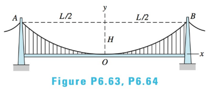
The two main cables of the Akashi Kaikyo suspension bridge in Japan have a span
Expert Solution & Answer

Trending nowThis is a popular solution!

Students have asked these similar questions
Find the internal forces N, V, M at point C and D of the three-hinged
parabolic arch shown.
22 kip/ft
10 kip
20 ft
10 ft
12 ft
B V
А
30 ft
30 ft
->
Determine the magnitude of the moment (in kip-ft) at B of member BC of
the frame shown below. Assume A, D, and E are pinned and Band C are
rigid joints.
5 k/ft
В
IABC = 800 in
6 ft
6 ft
18 ft-
20 k
IBD = 600 in*
%3D
6 ft
ICE = 1000 in*
%3D
|D
A beam (AB) is supported by a roller at B and a pin at A. It is subjected to the following uniform distributed loads.
Determine the reaction force at roller B.
9 kN/m
6 kN/m
3 kN/m
1.5 m
3m
15m
Chapter 6 Solutions
International Edition---engineering Mechanics: Statics, 4th Edition
Ch. 6 - Determine the internal force system acting on...Ch. 6 - Determine the internal force system acting on...Ch. 6 - Determine the internal force system acting on...Ch. 6 - Find the internal force systems acting on sections...Ch. 6 - Find the internal force systems acting on sections...Ch. 6 - Find the internal force systems acting on sections...Ch. 6 - The three identical cantilever beams carry...Ch. 6 - Determine the internal force systems acting on...Ch. 6 - For the structural component shown, determine the...Ch. 6 - Compute the internal force system acting on...
Ch. 6 - Determine the internal force system acting on...Ch. 6 - Determine the internal force systems acting on...Ch. 6 - Determine the internal force systems acting on...Ch. 6 - Find the internal force system acting on section 3...Ch. 6 - The structure is supported by a pin at C and a...Ch. 6 - The 1800lbin. couple is applied to member DEF of...Ch. 6 - A man of weight W climbs a ladder that has been...Ch. 6 - For the ladder in Prob. 6.17, find the internal...Ch. 6 - Determine the internal force system acting on...Ch. 6 - The equation of the parabolic arch is y=(36x2)/6,...Ch. 6 - For the beam shown, derive the expressions for V...Ch. 6 - For the beam shown, derive the expressions for V...Ch. 6 - For the beam shown, derive the expressions for V...Ch. 6 - For the beam shown, derive the expressions for V...Ch. 6 - For the beam shown, derive the expressions for V...Ch. 6 - For the beam shown, derive the expressions for V...Ch. 6 - For the beam shown, derive the expressions for V...Ch. 6 - For the beam shown, derive the expressions for V...Ch. 6 - For the beam shown, derive the expressions for V...Ch. 6 - For the beam shown, derive the expressions for V...Ch. 6 - For the beam shown, derive the expressions for V...Ch. 6 - For the beam shown, derive the expressions for V...Ch. 6 - For the beam shown, derive the expressions for V...Ch. 6 - For the beam shown, derive the expressions for V...Ch. 6 - For the beam shown, derive the expressions for V...Ch. 6 - For the beam shown, derive the expressions for V...Ch. 6 - For the beam shown, derive the expressions for V...Ch. 6 - For the beam shown, derive the expressions for V...Ch. 6 - Derive the shear force and the bending moment as...Ch. 6 - Derive the shear force and the bending moment as...Ch. 6 - The 24-ft timber floor joist is designed to carry...Ch. 6 - For the beam AB shown in Cases 1 and 2, derive and...Ch. 6 - Construct the shear force and bending moment...Ch. 6 - Construct the shear force and bending moment...Ch. 6 - Construct the shear force and bending moment...Ch. 6 - Construct the shear force and bending moment...Ch. 6 - Construct the shear force and bending moment...Ch. 6 - Construct the shear force and bending moment...Ch. 6 - Construct the shear force and bending moment...Ch. 6 - Construct the shear force and bending moment...Ch. 6 - Construct the shear force and bending moment...Ch. 6 - Construct the shear force and bending moment...Ch. 6 - Construct the shear force and bending moment...Ch. 6 - Construct the shear force and bending moment...Ch. 6 - Construct the shear force and bending moment...Ch. 6 - Construct the shear force and bending moment...Ch. 6 - Draw the load and the bending moment diagrams that...Ch. 6 - Draw the load and the bending moment diagrams that...Ch. 6 - Draw the load and the bending moment diagrams that...Ch. 6 - Draw the load and the bending moment diagrams that...Ch. 6 - Draw the load and the bending moment diagrams that...Ch. 6 - Show that the tension acting at a point in a...Ch. 6 - The cable of the suspension bridge spans L=140m...Ch. 6 - The two main cables of the Akashi Kaikyo...Ch. 6 - Cable AB supports the uniformly distributed load...Ch. 6 - A uniform 80-ft pipe that weighs 960 lb is...Ch. 6 - The cable AB supports a uniformly distributed load...Ch. 6 - The string attached to the kite weighs 0.4 oz/ft....Ch. 6 - Show that the tension acting at a point in a...Ch. 6 - A uniform cable weighing 16 N/m is suspended from...Ch. 6 - The tensions in the cable at points O and B are...Ch. 6 - The cable AOB weighs 24 N/m. Determine the sag H...Ch. 6 - The cable of mass 1.8 kg/m is attached to a rigid...Ch. 6 - One end of cable AB is fixed, whereas the other...Ch. 6 - The end of a water hose weighing 0.5 lb/ft is...Ch. 6 - The 50-ft measuring tape weighs 2.4 lb. Compute...Ch. 6 - The cable AOB weighs 5.2 N/m. When the horizontal...Ch. 6 - The chain OA is 25 ft long and weighs 5 lb/ft....Ch. 6 - The 110-lb traffic light is suspended from two...Ch. 6 - The cable carrying 60-lb loads at B and C is held...Ch. 6 - The cable ABCD is held in the position shown by...Ch. 6 - Find the forces in the three cable segments and...Ch. 6 - The cable carrying three 400-lb loads has a sag at...Ch. 6 - The cable supports three 400-lb loads as shown. If...Ch. 6 - Cable ABC of length 5 m supports the force W at B....Ch. 6 - When the 12-kN load and the unknown force P are...Ch. 6 - The cable is loaded by an 80-lb vertical force at...Ch. 6 - The 15-m-long cable supports the loads W1 and W2...Ch. 6 - The cable of length 15 m supports the forces...Ch. 6 - The 14-kN weight is suspended from a small pulley...Ch. 6 - For the cable ABCD determine (a) the angles 2 and...
Knowledge Booster


Learn more about
Need a deep-dive on the concept behind this application? Look no further. Learn more about this topic, mechanical-engineering and related others by exploring similar questions and additional content below.Similar questions
- The compound beam is supported by a roller at point C, fixed at point A, and the two sections are pinned at point B. It is subjected to a free couple moment M, a distributed load with maximum load intensity w, and a concentrated force F. If the distributed load w = 0.6 kN/m, the concentrated force F = 0.6 kN, and the free couple moment M = 0.8, determine the magnitude of the support reaction (in kN) at pin B. Answer must include 2 places after the decimal point.arrow_forwardDetermine the support reactions at the the fixed support, A. Neglect the weight and size of the beam. Given data: Distributed load W=50 N/m; Couple C=160 N-m; and the point load P-780 N acting inclined at an angle of 35 in degree with respect to horizontal. W (n/m) P C (N.m) 1.5 m 2 m 4 m Horizontal force component at A along x, AxD Horizontal force component at A along y, Ay= Moment component at A, Ma= N. marrow_forwardRope BCA passes through a pulley at point C and supports a crate at point A. Rope segment CD supports the pulley and is attached to an eye anchor embedded in a wall. Rope segment BC creates an angle of ¢ = 64.0 ° with the floor and rope segment CD creates an angle 0 with the horizontal. If both ropes BCA and CD can support a maximum tensile force Tmaz = 165 lb , what is the maximum weight Wmax of the crate that the system can support? What is the angle 0 required for D equilibrium? Express your answers numerically in pounds and degrees to three significant figures separated by a comma. • View Available Hint(s) vec ? Wmax, 0 = lb, degreesarrow_forward
- A tie plate is used to transmit three-bar forces to a beam as shown in the figure. The modulus of the resultant R of the three forces is 100 kN. If the force F1 has a modulus of 20 kN, determine the moduli of the forces F2 and F3arrow_forwardFind the reaction at A due to the uniform loading and the applied couple. The force reaction is positive if upward, negative if downward. The moment reaction is positive if counterclockwise, negative if clockwise. 2.5 kN/m 11.1 kN-m A 2.0 m 2.0 m Answers: RA = i kN MA = i kN-marrow_forwardRope BCA passes through a pulley at point C and supports a crate at point A. Rope segment CD supports the pulley and is attached to an eye anchor embedded in a wall. Rope segment BC creates an angle of ø = 64.0 ° with the floor and rope segment CD creates an angle 0 with the horizontal. If both ropes BCA and CD can support a maximum tensile force Tmaz = 165 lb. what is the maximum weight Wmar of the crate that the system can support? What is the angle e required for equilibrium? Express your answers numerically in pounds and degrees to three significant figures separated by a comma. • View Available Hint(s) nν ΑΣφ vec Wmax.0 = lb, degreesarrow_forward
- A bent pipe is connected by a thrust bearing and a cable as shown. If a Force, F = 184 lb, is applied, what are the reactions at the thrust bearing and in the cable. The dimensions shown are a = 8.7 ft, b = 6.4 ft, and c = 4.5 ft. y Narrow_forwardHinge supported beam is loaded by two concentrated forces and a couple. M F. F, Given: 4=40cm; 2=80cm; l3=80cm; F1= -120N; F2= -390N; M= 100N·m. Find: algebraical value of reactive force (in N) of movable hinge (right support), considering it to be positive if directed upwards and negative if downwards. Ответ:arrow_forwardF1 2m F2 A 3.2m 1.8m AF, = 153 N load and a F, = 99 N are applied to the frame which is supported by pins at A and B. These loads are applied perpendicular to the beams. The two beams AC and BC make a right triangle. You may neglect the weight of the members. Find the magnitude of the force at pin C. For this problem, use the coordinate frame given. 1.5 m 4------ 1.5 m +----- 2.4marrow_forward
- QUESTION 1 Determine the reaction moment at x = 0 in kN-m. QUESTION 2 Determine the vertical reaction force at x = 0 in kN. QUESTION 3 (1-3) Determine the horizontal reaction force at x = 0 in kN. The distributed load, f(x), is equal to 100 kN/m. /// f(x) 3 marrow_forward6 m FB Fc 2m- 3 m. 3 m Problem 03. (C-EVEN) Determine the magnitude and direction angles of the resultant force acting on the flag pole. = 700 N FB = 560N and Fcarrow_forwardam of Mechanics/Firs X E Monthly Exam of Mechanics/Firs x PQLS ZSh4aZJdw9EBqROOfLVx M7KUGF6 9bgBbd-YGOXA/formResponse * For the force shown in figure, find the resultant (R) by component method F=10 kN 0=30° R=5 kN R=10 KN O R=15 kN O R=60 KN For the forces shown in figure, find just (EFx) components F=4 kN F=2 kN 0-30 A=300arrow_forward
arrow_back_ios
SEE MORE QUESTIONS
arrow_forward_ios
Recommended textbooks for you
 Elements Of ElectromagneticsMechanical EngineeringISBN:9780190698614Author:Sadiku, Matthew N. O.Publisher:Oxford University Press
 Mechanics of Materials (10th Edition)Mechanical EngineeringISBN:9780134319650Author:Russell C. HibbelerPublisher:PEARSON
 Thermodynamics: An Engineering ApproachMechanical EngineeringISBN:9781259822674Author:Yunus A. Cengel Dr., Michael A. BolesPublisher:McGraw-Hill Education
 Control Systems EngineeringMechanical EngineeringISBN:9781118170519Author:Norman S. NisePublisher:WILEY
 Mechanics of Materials (MindTap Course List)Mechanical EngineeringISBN:9781337093347Author:Barry J. Goodno, James M. GerePublisher:Cengage Learning
 Engineering Mechanics: StaticsMechanical EngineeringISBN:9781118807330Author:James L. Meriam, L. G. Kraige, J. N. BoltonPublisher:WILEY
Elements Of Electromagnetics
Mechanical Engineering
ISBN:9780190698614
Author:Sadiku, Matthew N. O.
Publisher:Oxford University Press
Mechanics of Materials (10th Edition)
Mechanical Engineering
ISBN:9780134319650
Author:Russell C. Hibbeler
Publisher:PEARSON
Thermodynamics: An Engineering Approach
Mechanical Engineering
ISBN:9781259822674
Author:Yunus A. Cengel Dr., Michael A. Boles
Publisher:McGraw-Hill Education
Control Systems Engineering
Mechanical Engineering
ISBN:9781118170519
Author:Norman S. Nise
Publisher:WILEY
Mechanics of Materials (MindTap Course List)
Mechanical Engineering
ISBN:9781337093347
Author:Barry J. Goodno, James M. Gere
Publisher:Cengage Learning
Engineering Mechanics: Statics
Mechanical Engineering
ISBN:9781118807330
Author:James L. Meriam, L. G. Kraige, J. N. Bolton
Publisher:WILEY
Mechanics of Materials Lecture: Beam Design; Author: UWMC Engineering;https://www.youtube.com/watch?v=-wVs5pvQPm4;License: Standard Youtube License