
International Edition---engineering Mechanics: Statics, 4th Edition
4th Edition
ISBN: 9781305501607
Author: Andrew Pytel And Jaan Kiusalaas
Publisher: CENGAGE L
expand_more
expand_more
format_list_bulleted
Concept explainers
Videos
Textbook Question
Chapter 6, Problem 6.85P
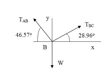
Cable ABC of length 5 m supports the force W at B. Determine (a) the angles
Expert Solution & Answer
Want to see the full answer?
Check out a sample textbook solution
Students have asked these similar questions
When the load L is 8.1 m from point C, the tension T in the cable has a magnitude of 6.9 kN. Express T as a vector using the unit vectors i and j. Assume a = 8.1 m, b = 4 m, c = 7.0m.
Replace the system of forces acting on the frame as shown by a
resultant R at A and a couple acting horizontally through B and C. Force
on top 10 kN, bottom left is 40 kN, and bottom right is 50 kN.
1m
A
3 m
2 m
4 m
OR= 20KN, B = 95KN, C= -95KN
OR- -20KN, B = -95kN, C = 95KN
OR= 20KN, B = -95KN, C = 95kN
OR=-20KN, B = 95KN, C = -95kN
mathalino,com
The jib crane shown in the figure is subjected to three coplanar forces. Replace this loading by an equivalent resultant force and
specify where the resultant's line of action intersects the column AB and boom BC.
y
3 ft
5 ft
3 ft
B,
C
6 ft
60 lb
250 lb
175 lb
5 ft
A
Chapter 6 Solutions
International Edition---engineering Mechanics: Statics, 4th Edition
Ch. 6 - Determine the internal force system acting on...Ch. 6 - Determine the internal force system acting on...Ch. 6 - Determine the internal force system acting on...Ch. 6 - Find the internal force systems acting on sections...Ch. 6 - Find the internal force systems acting on sections...Ch. 6 - Find the internal force systems acting on sections...Ch. 6 - The three identical cantilever beams carry...Ch. 6 - Determine the internal force systems acting on...Ch. 6 - For the structural component shown, determine the...Ch. 6 - Compute the internal force system acting on...
Ch. 6 - Determine the internal force system acting on...Ch. 6 - Determine the internal force systems acting on...Ch. 6 - Determine the internal force systems acting on...Ch. 6 - Find the internal force system acting on section 3...Ch. 6 - The structure is supported by a pin at C and a...Ch. 6 - The 1800lbin. couple is applied to member DEF of...Ch. 6 - A man of weight W climbs a ladder that has been...Ch. 6 - For the ladder in Prob. 6.17, find the internal...Ch. 6 - Determine the internal force system acting on...Ch. 6 - The equation of the parabolic arch is y=(36x2)/6,...Ch. 6 - For the beam shown, derive the expressions for V...Ch. 6 - For the beam shown, derive the expressions for V...Ch. 6 - For the beam shown, derive the expressions for V...Ch. 6 - For the beam shown, derive the expressions for V...Ch. 6 - For the beam shown, derive the expressions for V...Ch. 6 - For the beam shown, derive the expressions for V...Ch. 6 - For the beam shown, derive the expressions for V...Ch. 6 - For the beam shown, derive the expressions for V...Ch. 6 - For the beam shown, derive the expressions for V...Ch. 6 - For the beam shown, derive the expressions for V...Ch. 6 - For the beam shown, derive the expressions for V...Ch. 6 - For the beam shown, derive the expressions for V...Ch. 6 - For the beam shown, derive the expressions for V...Ch. 6 - For the beam shown, derive the expressions for V...Ch. 6 - For the beam shown, derive the expressions for V...Ch. 6 - For the beam shown, derive the expressions for V...Ch. 6 - For the beam shown, derive the expressions for V...Ch. 6 - For the beam shown, derive the expressions for V...Ch. 6 - Derive the shear force and the bending moment as...Ch. 6 - Derive the shear force and the bending moment as...Ch. 6 - The 24-ft timber floor joist is designed to carry...Ch. 6 - For the beam AB shown in Cases 1 and 2, derive and...Ch. 6 - Construct the shear force and bending moment...Ch. 6 - Construct the shear force and bending moment...Ch. 6 - Construct the shear force and bending moment...Ch. 6 - Construct the shear force and bending moment...Ch. 6 - Construct the shear force and bending moment...Ch. 6 - Construct the shear force and bending moment...Ch. 6 - Construct the shear force and bending moment...Ch. 6 - Construct the shear force and bending moment...Ch. 6 - Construct the shear force and bending moment...Ch. 6 - Construct the shear force and bending moment...Ch. 6 - Construct the shear force and bending moment...Ch. 6 - Construct the shear force and bending moment...Ch. 6 - Construct the shear force and bending moment...Ch. 6 - Construct the shear force and bending moment...Ch. 6 - Draw the load and the bending moment diagrams that...Ch. 6 - Draw the load and the bending moment diagrams that...Ch. 6 - Draw the load and the bending moment diagrams that...Ch. 6 - Draw the load and the bending moment diagrams that...Ch. 6 - Draw the load and the bending moment diagrams that...Ch. 6 - Show that the tension acting at a point in a...Ch. 6 - The cable of the suspension bridge spans L=140m...Ch. 6 - The two main cables of the Akashi Kaikyo...Ch. 6 - Cable AB supports the uniformly distributed load...Ch. 6 - A uniform 80-ft pipe that weighs 960 lb is...Ch. 6 - The cable AB supports a uniformly distributed load...Ch. 6 - The string attached to the kite weighs 0.4 oz/ft....Ch. 6 - Show that the tension acting at a point in a...Ch. 6 - A uniform cable weighing 16 N/m is suspended from...Ch. 6 - The tensions in the cable at points O and B are...Ch. 6 - The cable AOB weighs 24 N/m. Determine the sag H...Ch. 6 - The cable of mass 1.8 kg/m is attached to a rigid...Ch. 6 - One end of cable AB is fixed, whereas the other...Ch. 6 - The end of a water hose weighing 0.5 lb/ft is...Ch. 6 - The 50-ft measuring tape weighs 2.4 lb. Compute...Ch. 6 - The cable AOB weighs 5.2 N/m. When the horizontal...Ch. 6 - The chain OA is 25 ft long and weighs 5 lb/ft....Ch. 6 - The 110-lb traffic light is suspended from two...Ch. 6 - The cable carrying 60-lb loads at B and C is held...Ch. 6 - The cable ABCD is held in the position shown by...Ch. 6 - Find the forces in the three cable segments and...Ch. 6 - The cable carrying three 400-lb loads has a sag at...Ch. 6 - The cable supports three 400-lb loads as shown. If...Ch. 6 - Cable ABC of length 5 m supports the force W at B....Ch. 6 - When the 12-kN load and the unknown force P are...Ch. 6 - The cable is loaded by an 80-lb vertical force at...Ch. 6 - The 15-m-long cable supports the loads W1 and W2...Ch. 6 - The cable of length 15 m supports the forces...Ch. 6 - The 14-kN weight is suspended from a small pulley...Ch. 6 - For the cable ABCD determine (a) the angles 2 and...
Knowledge Booster


Learn more about
Need a deep-dive on the concept behind this application? Look no further. Learn more about this topic, mechanical-engineering and related others by exploring similar questions and additional content below.Similar questions
- The bracket, which is fastened to a wall by anchor bolts at A and B, is loaded by the force P = 140 N and the couple C = 180 N•m. Replace P and C with (a) an equivalent force-couple system, the force of which acts at A; and (b) two vertical forces, one acting at A and the other at B.arrow_forwardThe jib crane shown in the figure is subjected to three coplanar forces. Replace this loading by an equivalent resultant force and specify where the resultant's line of action intersects the column AB and boom BC. y 3 ft 5 ft 3 ft B. 6 ft 60 lb 250 lb 175 lb 5 ft Aarrow_forward6. The jib crane shown in the figure below is subjected to three coplanar forces. Replace this loading by an equivalent resultant force and specify the resultant's line of action intersects the column AB and boom BC. 175 lb- 6 ft 5 ft B 3 ft 5 ft 60 lb 250 lb 3 ft Carrow_forward
- k-i The tongs are used to grip the ends of the drilling pipe P. If a torque (moment) of Mp = 900 lb· ft is needed at point P to turn the pipe, determine the cable force F that must be applied to the tongs. Set 0 = 40°. (1 ft = 12 in.) 6 in. Mp 43 in. For question (Q2) above, if 0 = 80°, what do you think the cable force will be? (Circle one) A) increased B) decreased C) still the same! 6 in. Mp 43 in.arrow_forwardCompute the magnitude of the moment MO of the 220-lb force about the axis O-O.Assume F = 220 lb, d = 17 in., H = 10.8 in., h = 5.4 in., 36°, and 61°.arrow_forwardWhen the load L is 10.8 m from point C, the tension T in the cable has a magnitude of 6.2 kN. Express T as a vector using the unit vectors i and j. Assume a = 10.8 m, b = 4 m, c = 9.4m. B T L b + Answer: T = ( i+ i j) kN a -Xarrow_forward
- (25) 1. Draw the free body diagrams for the following system. Write the force equations. + Xi(t) X:(t) f(t)- B K2 M2arrow_forwardThe guy wires AB and AC are attached to the top of the transmission tower. The tension in cable AB is 7.3 kN. Determine the required tension T in cable AC such that the net effect of the two cables is a downward force at point A. Determine the magnitude R of this downward force.Assume a = 41 m, b = 48 m, c = 29 m, and d = 35 m.arrow_forward1. the tow truck's front wheels will belifted off the ground if the moment of the load W about the rear axle exceeds the moment of 3000N weight of the truck. Determine the largest w that may be safely applied 2. the flat plate shown in the figure is acted on by the three couples. replace the three couples with two forces, one acting along the line OParrow_forward
- Example : Replace the three forces acting on the bent beam by a single equivalent force R. Specify the distance x from the point O in which the line of action of R passes. 200 N 160 N 250 mm 250 mm -250 mm 125 mm 240 Narrow_forwardGiven a system made of the force F, couple M and distributed loads defined by w1 and w2, find the equivalent system at B.Take F = 8 kN, M = 5 kN.m, w1 = 8 kN/m, and w2 = 4 kN/m.Also, d = 1 m.arrow_forwardThe crate weighing 400 lb is supported by three ropes concurrent at B.Find the forces in ropes AB and BC if P = 460 lb.arrow_forward
arrow_back_ios
SEE MORE QUESTIONS
arrow_forward_ios
Recommended textbooks for you
 International Edition---engineering Mechanics: St...Mechanical EngineeringISBN:9781305501607Author:Andrew Pytel And Jaan KiusalaasPublisher:CENGAGE L
International Edition---engineering Mechanics: St...
Mechanical Engineering
ISBN:9781305501607
Author:Andrew Pytel And Jaan Kiusalaas
Publisher:CENGAGE L
Engineering Basics - Statics & Forces in Equilibrium; Author: Solid Solutions - Professional Design Solutions;https://www.youtube.com/watch?v=dQBvQ2hJZFg;License: Standard YouTube License, CC-BY