Concept explainers
Videos
The force in each of the members of the truss for
Answer to Problem 6.36P
The force in member AC is
Explanation of Solution
The free-body diagram of the entire truss is shown in figure 1.
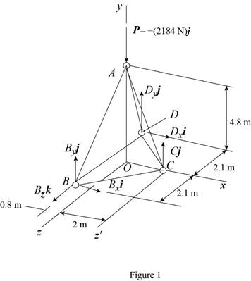
Refer to figure 1 and use symmetry.
Here,
The
Here,
Write the expression for
Put the above equation in equation (II).
Put equation (I) in the above equation.
The
Here,
Write the expression for
Here,
Put the above equation in equation (III).
Write the equilibrium equations taking the moments about the point C in the
Here,
Write the equation for
Put the above equation in equation (IV).
Write the expression for the reaction at the point B.
Here
Substitute
Consider the free-body joint A. The free-body diagram of joint A is shown in figure 2.
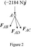
Refer to figure (2) and write the expression for the forces.
Here,
Write the expression for
Find the magnitude of
Substitute
Write the expression for
Here,
Substitute
Write the expression for
Here,
Substitute
The net force must be equal to zero.
Here,
Write the expression for
Put the above equation in equation (IX).
Put equations (VI), (VII) and (VIII) in the above equation.
Equate the coefficient of
Equate the coefficient of
Equate the coefficient of
Multiply equation (XI) by
Put equation (XIII) in equation (XI).
Substitute
Put the above equation in equation (XIII).
Consider the free-body joint B. The free-body diagram of joint B is shown in figure 3.
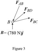
Refer to figure (3) and write the expression for the forces.
Substitute
Write the expression for
Here,
Substitute
Write the expression for
Here,
Write the expression for
Put the above equation in equation (IX).
Put equations (XIV), (XV) and (XVI) in the above equation.
Substitute
Equate the coefficient of
Equate the coefficient of
Substitute
From symmetry,
Here,
Substitute
Conclusion:
Thus, the force in member AC is
Want to see more full solutions like this?
Chapter 6 Solutions
Loose Leaf for Vector Mechanics for Engineers: Statics and Dynamics


- Determine the force in each member of the loaded truss. The forces are positive if in tension, negative if in compression. Assume F1 = 3600 lb, F2 = 3200 lb, a=4.1 ft, b=6.6 ft, c=2.2 ft, d=3.2 ftarrow_forward3. Determine the force in each member of the loaded truss. Indicate if it is tension or compression. Assume F = 3090 N, a = 3.5 m, b = 7.0 m, 0= 49°. A D B a Farrow_forwardDetermine the force in each member of the space truss given F-3 kN. Use positive to indicate tension and negative to indicate compression. Z D FAB= 5.35 FAC = 1.25 FAD = 1.25 FBC= 3.08 FBD = 3.08 FBE = 4 3 m E 2 m 3 m 4 m. x kN X KN X KN x kN x kN X KN B 5 m A F yarrow_forward
- Determine the force in truss members BC and EC and indicate whether they are in tension or compression. Consider P=7 (kN)arrow_forwardCalculate the forces in members BC, BE, and EF. Solve for each force from an equilibrium equation which contains that force as the only unknown. Modification: Change load to 8.9 kN, length of members AG and BF to 4m. Use the method of sections 14 kN A 3 m В 3 m C 3 m 2 m 3 m 3 m E G Farrow_forwardDetermine the force in each member of the loaded truss. The forces are positive if in tension, negative if in compression. Assume F1 = 4070 Ilb, F2 = 4680 lb, a = 4.3 ft, b = 6.3 ft, c = 2.4 ft, and d= 3.5 ft. E Answers: AB = ! Ib AE = ! Ib BC = Ib BD = Ib BE = ! Ib CD = Ib DE = i Ibarrow_forward
- Approximately determine the forces in each member of the truss. Assume that the diagonal members work in both tension and compression. 3 KN 3 kN 3 kN 6 m 6 m B 6 m 3 kN tal 6m 3 kN 3 kNarrow_forwardCalculate the forces in members BC, BE, and EF. Solve for each force from an equilibrium equation which contains that force as the only unknown. The forces are positive if in tension, negative if in compression. 3.0 m BC= Answers: BE= A 3.0 m EF= G i i i B 3.0 m 3.0 m F 1.9 m E 3.0 m 20.0 KN KN KN kN Darrow_forwardDetermine the force in members LK, KC, and CD of the Pratt truss. State if the members are in tension or compression. Take that P₁ = 19 kN, P₂ = 31 kN and P3 = 42 kN.(Figure 1) Figure 3 m B C -2 m2 m K P₁ P2 DE H P3 F 1 of 1 > m2 m2 m--2 m-arrow_forward
- Using the attached image, determine the force in each member of the truss and state if the members are in tension or compression. Set P1= 2 kN and P2= 1.5 kN. Use method of joint.arrow_forwardDetermine the force in members LK, KC, and CD of the Pratt truss. State if the members are in tension or compression. Take that P₁ = 21 kN, P₂ = 31 kN and P3 = 42 kN.(Figure 1) Figure 3 m T2m- K B C D E P₁ P₂ P3 H F 1 of 1 m2 m2 m2 m2 m--2 m-arrow_forwardDetermine the force in members CD and DF of the truss shown when P = 13 kN. 5 m <3 m3 m3 m3 m P P P C E A B The force in CD is The force in DF is D F kN. (Click to select) kN. (Click to select) H V G V P SIarrow_forward
 Elements Of ElectromagneticsMechanical EngineeringISBN:9780190698614Author:Sadiku, Matthew N. O.Publisher:Oxford University Press
 Mechanics of Materials (10th Edition)Mechanical EngineeringISBN:9780134319650Author:Russell C. HibbelerPublisher:PEARSON
 Thermodynamics: An Engineering ApproachMechanical EngineeringISBN:9781259822674Author:Yunus A. Cengel Dr., Michael A. BolesPublisher:McGraw-Hill Education
 Control Systems EngineeringMechanical EngineeringISBN:9781118170519Author:Norman S. NisePublisher:WILEY
 Mechanics of Materials (MindTap Course List)Mechanical EngineeringISBN:9781337093347Author:Barry J. Goodno, James M. GerePublisher:Cengage Learning
 Engineering Mechanics: StaticsMechanical EngineeringISBN:9781118807330Author:James L. Meriam, L. G. Kraige, J. N. BoltonPublisher:WILEY