Videos
The force exerted by each cylinder shown in figure
Answer to Problem 6.158P
The force exerted by the cylinder
Explanation of Solution
Take all
Let P is the force exerted on the bucket at J.
The magnitude of force
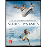
The free body diagram of the bucket is sketched below as figure 1.
Here,
Write the expression for the moment at
Here,
Above equation implies that net moment at any point is the sum of product of each force acting on the system and perpendicular distance of the force and the point.
The moment at
Thus, the complete expression of net anticlockwise moment
Here,
At equilibrium, the sum of the moment acting at
Write the expression for the total moment acting at
From figure 1 , write the expression for the
From figure 1 , write the expression for the
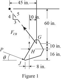
The free body diagram of the bucket and arm
Here,
Write the expression for the moment at
Here,
Above equation implies that net moment at any point is the sum of product of each force acting on the system and perpendicular distance of the force and the point.
The moment at
Thus, the complete expression of net anticlockwise moment
Here,
At equilibrium, the sum of the moment acting at
Write the expression for the total moment acting at
From figure 2 , write the expression for the
Geometry of cylinder
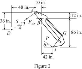
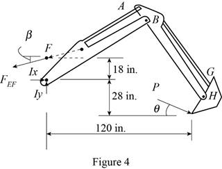
The free body diagram of the bucket and both arms is sketched below as figure 4.
Here,
Write the expression for the moment at
Here,
Above equation implies that net moment at any point is the sum of product of each force acting on the system and perpendicular distance of the force and the point.
The moment at
Thus, the complete expression of net anticlockwise moment
Here,
At equilibrium, the sum of the moment acting at
Write the expression for the total moment acting at
From figure 3 , write the expression for the
Calculation:
Substitute
The negative sign indicate that the cylinder undergoes compression.
Substitute
The negative sign indicate that the cylinder undergoes compression.
Rearrange the equation (X) to get

Substitute
The positive sign indicate that the cylinder
Therefore, the force exerted by the cylinder
Want to see more full solutions like this?
Chapter 6 Solutions
Loose Leaf for Vector Mechanics for Engineers: Statics and Dynamics


- (1) A 50 lb roller, with diameter 10 in, is used to level a tile floor, and is resting directly on the subflooring as shown. If the thickness of the tile is 30° 0.25 in, what is the minimum force P required to pull the roller onto the tiles when it is pulled slowly to the right? Fig. P4.75 and P4.76arrow_forwardKnowing that the radius of each pulley is 130 mm and neglecting friction, external force is 297 N. Determine the internal forces at Points J and K of the frame shown. Solution: 1. FBD for frame and pulleys together: a. There are b. Sum moment about point c. Sum all the horizonal forces to zero, solve that Ax = = d. Sum all the vertical forces to zero, yield that Ay + By 2. FBD for Member AE: a. There are supports on the frame, they are both c. Thus By b. Sum moment about point = a. There are solve that Bx = d. Sum all the horizontal forces to zero, solve that Ex N; direction is pointing to the 3. FBD for AK to determine the internal forces on K: forces/reactions on the member AE, for a 2D body, this is statically a. There are forces/reactions on the AK; b. Sum axial forces to zero, solve that nominal force FK d. Sum moment about point and note that the tension force in the cable on D is c. Sum tangential forces to zero, solve that shear force VK = 4. FBD for BJ to determine the…arrow_forwardKnowing that a worker applies forces of magnitude P = 135 N to the han- dles, determine the magnitude of the crimping forces that are exerted on the 140 The tool shown is used to crimp terminals onto electric wires. terminal. 30 +40- 200 B D F C E 15 Dimensions in mm -P Fig. P6.140arrow_forward
- The force P has a magnitude of 250 N and is applied at the end C of a 500-mm rod AC attached to a bracket at A and B. Assuming α =30° and β=60°, replace P with (a) an equivalent force-couple system at B, (b) an equivalent system formed by two parallel forces applied at A and B.arrow_forward4.95 The linkage of the braking system consists of the pedal arm DAB, the connecting rod BC, and the hydraulic cylinder C. At what angle 0 will the force Q be four times greater than the force P applied to the pedal? Neglect friction and the weight of the linkage. 250 mm Fig. P4.95 100 mm -100 mmarrow_forwardProblem 4.116 Determine the sum of the moments exerted about A by the couple and the two forces. 100 Ib 1400 Ib 900 ft-lb Ans. M=2200 c.w 4 Rarrow_forward
- The pipe ABCDE is supported by ball-and-socket joints at A and D and by cable ECF that passes through a ring C with negligible friction and is attached to hooks at E and F. Knowing that the frame supports a uniformly distributed load of 1500 N/m along segment AB, do the following.1) Shows the correct vector representation of the resultant of the two tension forces acting at ring C. Note that T_CF = T_CE = T2) Explain along which line/axis you can sum moments to generate an equilibrium equation with only the magnitude of the tension force as the unknown. Explain your choice.3) Find the magnitude of the tension force.arrow_forward4.81 When activated by the force P, the gripper on a robotic arm is able to pick up objects by applying the gripping force F. Given that P = 120 N, calculate the gripping force for the position shown. 160 mm - 250 mm 52 mm- B m m. D m m. Fig. P4.81arrow_forward360 mm 920 mm lo 600 mm 900 mm C.arrow_forward
- The uniform 10 kg rod AB is supported by a ball and socket joint at A and by the cord CG that is attached to the midpoint G of the rod. Knowing that the rod leans against a frictionless vertical wall at B and that the tension in the cord CG, TCG=52.1 N, determine the following, Which of the following best approximates the moment of the weight of the structure about A? Choices: (7.36i + 29.4k) N-m(7.36i + 29.4j) N-m(29.4i + 7.36k) N-m(29.4i + 7.36j) N-marrow_forwardDetermine the components of force P= 40 kN along x and y as shown in Fig.?. (16) Pe4oKN 30arrow_forwardProblem 1.- A stake is being pulled out of the ground by means of two ropes as shown. Knowing that the tension in one rope is 120 N, determine by trigonometry the magnitude and direction of the force P so that the resultant is a vertical force of 160 N. Answer: P = 72.1 N and a = 44.7° %3D 120 N 25arrow_forward
 Elements Of ElectromagneticsMechanical EngineeringISBN:9780190698614Author:Sadiku, Matthew N. O.Publisher:Oxford University Press
 Mechanics of Materials (10th Edition)Mechanical EngineeringISBN:9780134319650Author:Russell C. HibbelerPublisher:PEARSON
 Thermodynamics: An Engineering ApproachMechanical EngineeringISBN:9781259822674Author:Yunus A. Cengel Dr., Michael A. BolesPublisher:McGraw-Hill Education
 Control Systems EngineeringMechanical EngineeringISBN:9781118170519Author:Norman S. NisePublisher:WILEY
 Mechanics of Materials (MindTap Course List)Mechanical EngineeringISBN:9781337093347Author:Barry J. Goodno, James M. GerePublisher:Cengage Learning
 Engineering Mechanics: StaticsMechanical EngineeringISBN:9781118807330Author:James L. Meriam, L. G. Kraige, J. N. BoltonPublisher:WILEY