
Microelectronics: Circuit Analysis and Design
4th Edition
ISBN: 9780073380643
Author: Donald A. Neamen
Publisher: McGraw-Hill Companies, The
expand_more
expand_more
format_list_bulleted
Videos
Textbook Question
Chapter 7, Problem 7.10P
(a) Determine the transfer function corresponding to the Bode plot of themagnitude shown in Figure P7.10. (b) What is the actual gain at(i)
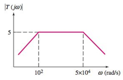
Figure P7.10
Expert Solution & Answer
Want to see the full answer?
Check out a sample textbook solution
Students have asked these similar questions
The impedance value of an RLC circuit is 30 N (as maximum value), during a
resonance with 60 Hz. BW is 20 Hz for the resonance point.
a) Draw the circuit and calculate the R, L, C values.
b) If we supply a signal with 50 Hz to this circuit, what do you think about the
characteristic behavior of the circuit?
Reduce the circuits and calculate the natural frequencies (ω0) and damped resonance frequencies (ωd) for both circuits.
In an image come support formulas
It is possible to detect the phase modulated signal non coherently.
Select one:
True
False
Chapter 7 Solutions
Microelectronics: Circuit Analysis and Design
Ch. 7 - (a) For the circuit shown in Figure 7.2, the...Ch. 7 - The circuit shown in Figure 7.10 has parameters of...Ch. 7 - For the equivalent circuit shown in Figure 7.13,...Ch. 7 - The equivalent circuit in Figure 7.14 has circuit...Ch. 7 - The parameters in the circuit shown in Figure 7.15...Ch. 7 - For the circuit shown in Figure 7.2 1(a), the...Ch. 7 - Consider the circuit shown in Figure 7.22(a). The...Ch. 7 - For the emitterfollower circuit shown in Figure...Ch. 7 - The circuit shown in Figure 7.27(a) has parameters...Ch. 7 - Consider the common-base circuit shown in Figure...
Ch. 7 - The commonemitter circuit shown in Figure 7.34...Ch. 7 - A bipolar transistor has parameters o=120 ,...Ch. 7 - Prob. 7.9EPCh. 7 - For the circuit in Figure 7.41(a), the parameters...Ch. 7 - A bipolar transistor is biased at ICQ=120A and its...Ch. 7 - For the transistor described in Example 7.9 and...Ch. 7 - The parameters of a bipolar transistor are: o=150...Ch. 7 - The parameters of an nchannel MOSFET are...Ch. 7 - For the circuit in Figure 7.55, the transistor...Ch. 7 - An nchannel MOSFET has parameters Kn=0.4mA/V2 ,...Ch. 7 - An nchannel MOSFET has a unitygain bandwidth of...Ch. 7 - For a MOSFET, assume that gm=1.2mA/V . The basic...Ch. 7 - The transistor in the circuit in Figure 7.60 has...Ch. 7 - Consider the commonbase circuit in Figure 7.64....Ch. 7 - The cascode circuit in Figure 7.65 has parameters...Ch. 7 - Prob. 7.12TYUCh. 7 - For the circuit in Figure 7.72, the transistor...Ch. 7 - Describe the general frequency response of an...Ch. 7 - Describe the general characteristics of the...Ch. 7 - Describe what is meant by a system transfer...Ch. 7 - What is the criterion that defines a corner, or...Ch. 7 - Describe what is meant by the phase of the...Ch. 7 - Describe the time constant technique for...Ch. 7 - Describe the general frequency response of a...Ch. 7 - Sketch the expanded hybrid model of the BJT.Ch. 7 - Prob. 9RQCh. 7 - Prob. 10RQCh. 7 - Prob. 11RQCh. 7 - Sketch the expanded smallsignal equivalent circuit...Ch. 7 - Define the cutoff frequency for a MOSFET.Ch. 7 - Prob. 14RQCh. 7 - Why is there not a Miller effect in a commonbase...Ch. 7 - Describe the configuration of a cascode amplifier.Ch. 7 - Why is the bandwidth of a cascode amplifier...Ch. 7 - Why is the bandwidth of the emitterfollower...Ch. 7 - Prob. 7.1PCh. 7 - Prob. 7.2PCh. 7 - Consider the circuit in Figure P7.3. (a) Derive...Ch. 7 - Consider the circuit in Figure P7.4 with a signal...Ch. 7 - Consider the circuit shown in Figure P7.5. (a)...Ch. 7 - A voltage transfer function is given by...Ch. 7 - Sketch the Bode magnitude plots for the following...Ch. 7 - (a) Determine the transfer function corresponding...Ch. 7 - Consider the circuit shown in Figure 7.15 with...Ch. 7 - For the circuit shown in Figure P7.12, the...Ch. 7 - The circuit shown in Figure 7.10 has parameters...Ch. 7 - The transistor shown in Figure P7.14 has...Ch. 7 - Consider the circuit shown in Figure P7.15. The...Ch. 7 - The transistor in the circuit shown in Figure...Ch. 7 - For the common-emitter circuit in Figure P7.17,...Ch. 7 - The transistor in the circuit in Figure P7.20 has...Ch. 7 - For the circuit in Figure P7.21, the transistor...Ch. 7 - (a) For the circuit shown in Figure P7.22, write...Ch. 7 - Consider the circuit shown in Figure P7.23. (a)...Ch. 7 - The parameters of the transistor in the circuit in...Ch. 7 - A capacitor is placed in parallel with RL in the...Ch. 7 - The parameters of the transistor in the circuit in...Ch. 7 - Prob. D7.27PCh. 7 - The circuit in Figure P7.28 is a simple output...Ch. 7 - Reconsider the circuit in Figure P728. The...Ch. 7 - Consider the circuit shown in Figure P7.32. The...Ch. 7 - The commonemitter circuit in Figure P7.35 has an...Ch. 7 - Consider the commonbase circuit in Figure 7.33 in...Ch. 7 - Prob. 7.39PCh. 7 - The parameters of the transistor in the circuit in...Ch. 7 - In the commonsource amplifier in Figure 7.25(a) in...Ch. 7 - A bipolar transistor has fT=4GHz , o=120 , and...Ch. 7 - A highfrequency bipolar transistor is biased at...Ch. 7 - (a) The frequency fT of a bipolar transistor is...Ch. 7 - The circuit in Figure P7.48 is a hybrid ...Ch. 7 - Consider the circuit in Figure P7.49. Calculate...Ch. 7 - A common-emitter equivalent circuit is shown in...Ch. 7 - For the common-emitter circuit in Figure 7.41(a)...Ch. 7 - For the commonemitter circuit in Figure P7.52,...Ch. 7 - Consider the circuit in Figure P7.52. The resistor...Ch. 7 - The parameters of the circuit shown in Figure...Ch. 7 - The parameters of an nchannel MOSFET are kn=80A/V2...Ch. 7 - Find fT for a MOSFET biased at IDQ=120A and...Ch. 7 - Fill in the missing parameter values in the...Ch. 7 - (a) An nchannel MOSFET has an electron mobility of...Ch. 7 - A commonsource equivalent circuit is shown in...Ch. 7 - Prob. 7.60PCh. 7 - The parameters of an ideal nchannel MOSFET are...Ch. 7 - Figure P7.62 shows the highfrequency equivalent...Ch. 7 - For the FET circuit in Figure P7.63, the...Ch. 7 - The midband voltage gain of a commonsource MOSFET...Ch. 7 - Prob. 7.65PCh. 7 - Prob. 7.67PCh. 7 - The bias voltages of the circuit shown in Figure...Ch. 7 - For the PMOS commonsource circuit shown in Figure...Ch. 7 - In the commonbase circuit shown in Figure P7.70,...Ch. 7 - Repeat Problem 7.70 for the commonbase circuit in...Ch. 7 - In the commongate circuit in Figure P7.72, the...
Knowledge Booster


Learn more about
Need a deep-dive on the concept behind this application? Look no further. Learn more about this topic, electrical-engineering and related others by exploring similar questions and additional content below.Similar questions
- For the following statements, identify which are True and which are False. If False, please explainin one or two sentences why the statement is False.a) Resonance in an RLC series circuit occurs when the driving frequency is equal to 5 times the natural frequencyof the circuit.b) The maximum power is delivered when the system is being driven at resonance.c) Damped spring-mass oscillators and RLC series circuits do not behave mathematically identically. At all. Period. Please clear explainations. Thnak youarrow_forwardCalculate the complex transfer function of the circuit. Write down expressions for the frequency response characteristic and phase response characteristics of the circuitarrow_forwardwhat are the magnitude and the phase angle of this transfer function?arrow_forward
- 7. a. The bandwidth of a series resonant circuit is 200 Hz. If the resonant frequency is 2000 Hz, what is the value of Q. for the circuit? b. If R = 22, what is the value of X₂ at resonance? c. Find the value of L and C at resonance. d. Find the cutoff frequencies.arrow_forwardb) What value of capacitance resonates with a 200-uH inductance at 1000 kHz? c) For an RLC circuit resonant at 900 KHz, the known components of the circuit are the following: a 10-ohm resistor and a 0.1-mH inductor. The circuit is connected to a 2 mVRMS ac source. Determine the voltage across each component, the quality factor and bandwidth. d) A tank circuit has upper and lower cutoff frequencies of 92.6 and 92.4 MHz. What is its resonant frequency and its bandwidth? If the inductor is 240-nH, what is the value of C?arrow_forwardBW mssege signai COTier. i) Draw the modulated signal in ii) find the bandwidth of the modulated signal ii) What is phase reversal and we could avoid it? frequency domain, (AM)arrow_forward
- Fill in your bole algebra training with karnaugh in the image.(Do not discount.)arrow_forwardDetermine the transfer function that produced the following Bode plot. (Note: the values here were chosen so that this transfer function could be determined exactly):arrow_forwardb. Choose the suitable choice foL ping of the following sentences 18 Maces 1. In order to tune a parallel resonant circuit to a lewer frequency the capacitor must a. Be increase. b. Be decrease. . BeZero. Remain the same 2. Ina very low frequency a series resonance behaves as Imost purely .......... circuit a Resistive. b Capacitive. . Inductive. d. Inductive and capacitive 3. Real part of the total impedance at resonance for complicated AC circuit is a. Positive Value. b. Zero Value. Negative Value. d. Complex value 4. For admittance locus the maximum obtained power factor is depend on a Maximum current b. Maximum voltage . Minimum power d. Minimum angle 5 Any non sinusoidal symmetrical waves are basically composite from fundamental wave plas .. of harmonics waves. aodd b. even . odd even d odd of even 6. If we append an inductance in series to an RL series circuit the time constant will be a Increases b. Decreases. Increases and Decreases. Increases or Decreases 7. The double energy…arrow_forward
- Find the transfer function for the circuit shown in the figure. Plot the amplitude graph of 2log10[H(jw)] and the phase angle graph of H(jw) Calculate the actual cutoff frequency? Calculate the true phase angle at the cutoff frequency?arrow_forward4. Given the following LRC circuit below: The circuit shown has a resonant frequency, fr=100 kHz. The circuit has a resistance value, R = 10002, capacitance value, C = 1.33nF. and an inductance value of L=1.904mH. a. Determine the quality factor, Q, for the circuit b. What is the BW of this circuit? c. Calculate the upper and lower cut-off frequencies. d. If the following triangle wave with a fundamental frequency, f, of 20 kHz is put through this filter, determine the output.arrow_forward= 44.2 V. (a) At what angular frequency An RLC circuit such as that of Figure (a) has R = 6.99 2, C = 24.7 µF, L = 1.23 H, and ɛm wd will the current amplitude have its maximum value, as in the resonance curves of Figure (b)? (b) What is this maximum value? At what (c) lower angular frequency wdi and (d) higher angular frequency wd2 will the current amplitude be half this maximum value? (e) What is (@d2 - wd1)/wd, the fractional half-width of the resonance curve for this circuit? R ll (a) R= 10 2 Xc> X1. X1 > X¢ ent amplitude Iarrow_forward
arrow_back_ios
SEE MORE QUESTIONS
arrow_forward_ios
Recommended textbooks for you
 Introductory Circuit Analysis (13th Edition)Electrical EngineeringISBN:9780133923605Author:Robert L. BoylestadPublisher:PEARSON
 Delmar's Standard Textbook Of ElectricityElectrical EngineeringISBN:9781337900348Author:Stephen L. HermanPublisher:Cengage Learning
 Programmable Logic ControllersElectrical EngineeringISBN:9780073373843Author:Frank D. PetruzellaPublisher:McGraw-Hill Education
 Fundamentals of Electric CircuitsElectrical EngineeringISBN:9780078028229Author:Charles K Alexander, Matthew SadikuPublisher:McGraw-Hill Education
 Electric Circuits. (11th Edition)Electrical EngineeringISBN:9780134746968Author:James W. Nilsson, Susan RiedelPublisher:PEARSON
 Engineering ElectromagneticsElectrical EngineeringISBN:9780078028151Author:Hayt, William H. (william Hart), Jr, BUCK, John A.Publisher:Mcgraw-hill Education,
Introductory Circuit Analysis (13th Edition)
Electrical Engineering
ISBN:9780133923605
Author:Robert L. Boylestad
Publisher:PEARSON
Delmar's Standard Textbook Of Electricity
Electrical Engineering
ISBN:9781337900348
Author:Stephen L. Herman
Publisher:Cengage Learning
Programmable Logic Controllers
Electrical Engineering
ISBN:9780073373843
Author:Frank D. Petruzella
Publisher:McGraw-Hill Education
Fundamentals of Electric Circuits
Electrical Engineering
ISBN:9780078028229
Author:Charles K Alexander, Matthew Sadiku
Publisher:McGraw-Hill Education
Electric Circuits. (11th Edition)
Electrical Engineering
ISBN:9780134746968
Author:James W. Nilsson, Susan Riedel
Publisher:PEARSON
Engineering Electromagnetics
Electrical Engineering
ISBN:9780078028151
Author:Hayt, William H. (william Hart), Jr, BUCK, John A.
Publisher:Mcgraw-hill Education,
Why Use Bode Plots? | Understanding Bode Plots, Part 1; Author: MATLAB;https://www.youtube.com/watch?v=F6-EaZobHNk;License: Standard Youtube License