
Vector Mechanics for Engineers: Statics and Dynamics
12th Edition
ISBN: 9781259638091
Author: Ferdinand P. Beer, E. Russell Johnston Jr., David Mazurek, Phillip J. Cornwell, Brian Self
Publisher: McGraw-Hill Education
expand_more
expand_more
format_list_bulleted
Videos
Textbook Question
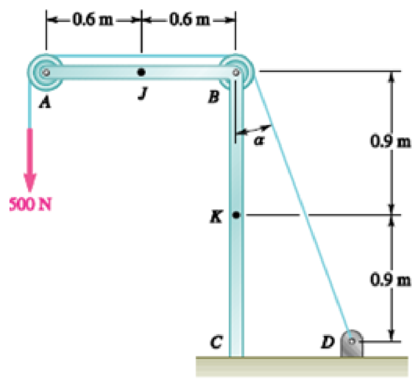
Chapter 7, Problem 7.157RP
Knowing that the radius of each pulley is 150 mm, that α = 20°, and neglecting friction, determine the internal forces at (a) point J, (b) point K.
Expert Solution & Answer
Want to see the full answer?
Check out a sample textbook solution
Students have asked these similar questions
Knowing that the radius of each pulley is 200 mm and neglecting friction, determine the internal forces at point J of the frame shown.
Knowing that the radius of each pulley is 130 mm and neglecting friction, external force is 297 N. Determine the internal forces at Points J and K of the frame shown.
Solution:
1. FBD for frame and pulleys together:
a. There are
b. Sum moment about point
c. Sum all the horizonal forces to zero, solve that Ax =
=
d. Sum all the vertical forces to zero, yield that Ay + By
2. FBD for Member AE:
a. There are
supports on the frame, they are both
c. Thus By
b. Sum moment about point
=
a. There are
solve that Bx =
d. Sum all the horizontal forces to zero, solve that Ex
N; direction is pointing to the
3. FBD for AK to determine the internal forces on K:
forces/reactions on the member AE, for a 2D body, this is statically
a. There are
forces/reactions on the AK;
b. Sum axial forces to zero, solve that nominal force FK
d. Sum moment about point
and note that the tension force in the cable on D is
c. Sum tangential forces to zero, solve that shear force VK =
4. FBD for BJ to determine the…
A winch at D is used to raise a 3000 Ilb load. The radii of winch D and pulley A are each
2ft. Assuming friction is negligible between the cable and the pulley, determine
a. The torque (Mp) required at D to raise the load at a constant velocity
b. Forces in members BC, EF, FG, and DG.
Q.3.
3'
3'
6'
T
B
C
D.
6'
E
G
F
1000 lb
650 lb
W
8'
H
Chapter 7 Solutions
Vector Mechanics for Engineers: Statics and Dynamics
Ch. 7.1 - 7.1 and 7.2 Determine the internal forces (axial...Ch. 7.1 - 7.1 and 7.2 Determine the internal forces (axial...Ch. 7.1 - Determine the internal forces at point J when =...Ch. 7.1 - Fig. P7.3 and P7.4 7.4 Determine the internal...Ch. 7.1 - Determine the internal forces at point J when =...Ch. 7.1 - Fig. P7.5 and P7.6 7.6 Determine the internal...Ch. 7.1 - An archer aiming at a target is pulling with a...Ch. 7.1 - For the bow of Prob. 7.7, determine the magnitude...Ch. 7.1 - A semicircular rod is loaded as shown. Determine...Ch. 7.1 - A semicircular rod is loaded as shown. Determine...
Ch. 7.1 - A semicircular rod is loaded as shown. Determine...Ch. 7.1 - Fig. P7.11 and P7.12 7.12 A semicircular rod is...Ch. 7.1 - The axis of the curved member AB is a parabola...Ch. 7.1 - Knowing that the axis of the curved member AB is a...Ch. 7.1 - Prob. 7.15PCh. 7.1 - Fig. P7.15 and P7.16 7.16 Knowing that the radius...Ch. 7.1 - Prob. 7.17PCh. 7.1 - For the frame of Prob. 7.17, determine the...Ch. 7.1 - Knowing that the radius of each pulley is 200 mm...Ch. 7.1 - Fig. P7.19 and P7.20 7.20 Knowing that the radius...Ch. 7.1 - and 7.22 A force P is applied to a bent rod that...Ch. 7.1 - and 7.22 A force P is applied to a bent rod that...Ch. 7.1 - Prob. 7.23PCh. 7.1 - For the rod of Prob. 7.23, determine the magnitude...Ch. 7.1 - A semicircular rod of weight W and uniform cross...Ch. 7.1 - Prob. 7.26PCh. 7.1 - Prob. 7.27PCh. 7.1 - 7.27 and 7.28 A half section of pipe rests on a...Ch. 7.2 - 7.29 through 7.32 For the beam and loading shown,...Ch. 7.2 - 7.29 through 7.32 For the beam and loading shown,...Ch. 7.2 - Prob. 7.31PCh. 7.2 - 7.29 through 7.32 For the beam and loading shown,...Ch. 7.2 - 7.33 and 7.34 For the beam and loading shown, (a)...Ch. 7.2 - 7.33 and 7.34 For the beam and loading shown, (a)...Ch. 7.2 - 7.35 and 7.36 For the beam and loading shown, (a)...Ch. 7.2 - Prob. 7.36PCh. 7.2 - 7.37 and 7.38 For the beam and loading shown, (a)...Ch. 7.2 - 7.37 and 7.38 For the beam and loading shown, (a)...Ch. 7.2 - For the beam and loading shown, (a) draw the shear...Ch. 7.2 - For the beam and loading shown, (a) draw the shear...Ch. 7.2 - Prob. 7.41PCh. 7.2 - For the beam and loading shown, (a) draw the shear...Ch. 7.2 - Assuming the upward reaction of the ground on beam...Ch. 7.2 - Solve Problem 7.43 knowing that P = 3wa. PROBLEM...Ch. 7.2 - Assuming the upward reaction of the ground on beam...Ch. 7.2 - Prob. 7.46PCh. 7.2 - Assuming the upward reaction of the ground on beam...Ch. 7.2 - Assuming the upward reaction of the ground on beam...Ch. 7.2 - Draw the shear and bending-moment diagrams for the...Ch. 7.2 - Draw the shear and bending-moment diagrams for the...Ch. 7.2 - Draw the shear and bending-moment diagrams for the...Ch. 7.2 - Draw the shear and bending-moment diagrams for the...Ch. 7.2 - Two small channel sections DF and EH have been...Ch. 7.2 - Solve Prob. 7.53 when = 60. PROBLEM 7.53 Two...Ch. 7.2 - For the structural member of Prob. 7.53, determine...Ch. 7.2 - For the beam of Prob. 7.43, determine (a) the...Ch. 7.2 - Determine (a) the distance a for which the maximum...Ch. 7.2 - For the beam and loading shown, determine (a) the...Ch. 7.2 - A uniform beam is to be picked up by crane cables...Ch. 7.2 - Knowing that P = Q = 150 lb, determine (a) the...Ch. 7.2 - Prob. 7.61PCh. 7.2 - Prob. 7.62PCh. 7.3 - Using the method of Sec. 7.3, solve Prob. 7.29....Ch. 7.3 - Prob. 7.64PCh. 7.3 - Prob. 7.65PCh. 7.3 - Using the method of Sec. 7.3, solve Prob. 7.32....Ch. 7.3 - Using the method of Sec. 7.3, solve Prob. 7.33....Ch. 7.3 - Using the method of Sec. 7.3, solve Prob. 7.34....Ch. 7.3 - 7.69 and 7.70 For the beam and loading shown, (a)...Ch. 7.3 - 7.69 and 7.70 For the beam and loading shown, (a)...Ch. 7.3 - Using the method of Sec. 7.3, solve Prob. 7.39....Ch. 7.3 - Using the method of Sec. 7.3, solve Prob. 7.40....Ch. 7.3 - Using the method of Sec. 7.3, solve Prob. 7.41....Ch. 7.3 - Using the method of Sec. 7.3, solve Prob. 7.42....Ch. 7.3 - 7.75 and 7.76 For the beam and loading shown, (a)...Ch. 7.3 - Prob. 7.76PCh. 7.3 - For the beam and loading shown, (a) draw the shear...Ch. 7.3 - For the beam and loading shown, (a) draw the shear...Ch. 7.3 - For the beam and loading shown, (a) draw the shear...Ch. 7.3 - For the beam and loading shown, (a) draw the shear...Ch. 7.3 - For the beam and loading shown, (a) draw the shear...Ch. 7.3 - For the beam and loading shown, (a) draw the shear...Ch. 7.3 - (a) Draw the shear and bending-moment diagrams for...Ch. 7.3 - Solve Prob. 7.83 assuming that the 300-lb force...Ch. 7.3 - For the beam and loading shown, (a) write the...Ch. 7.3 - For the beam and loading shown, (a) write the...Ch. 7.3 - For the beam and loading shown, (a) write the...Ch. 7.3 - Prob. 7.88PCh. 7.3 - The beam AB supports the uniformly distributed...Ch. 7.3 - Solve Prob. 7.89 assuming that the uniformly...Ch. 7.3 - The beam AB is subjected to the uniformly...Ch. 7.3 - Solve Prob. 7.91 assuming that the uniformly...Ch. 7.4 - Three loads are suspended as shown from the cable...Ch. 7.4 - Knowing that the maximum tension in cable ABCDE is...Ch. 7.4 - Prob. 7.95PCh. 7.4 - Fig. P7.95 and P7.96 7.96 If dA = dc = 6 ft,...Ch. 7.4 - Knowing that dc = 5 m, determine (a) the distances...Ch. 7.4 - Fig. P7.97 and P7.98 7.98 Determine (a) distance...Ch. 7.4 - Knowing that dc = 9 ft, determine (a) the...Ch. 7.4 - Fig. P7.99 and P7.100 7.100 Determine (a) the...Ch. 7.4 - Knowing that mB = 70 kg and mC = 25 kg, determine...Ch. 7.4 - Prob. 7.102PCh. 7.4 - Prob. 7.103PCh. 7.4 - Prob. 7.104PCh. 7.4 - Prob. 7.105PCh. 7.4 - If a = 4 m, determine the magnitudes of P and Q...Ch. 7.4 - An electric wire having a mass per unit length of...Ch. 7.4 - Prob. 7.108PCh. 7.4 - Prob. 7.109PCh. 7.4 - Prob. 7.110PCh. 7.4 - Prob. 7.111PCh. 7.4 - Two cables of the same gauge are attached to a...Ch. 7.4 - Prob. 7.113PCh. 7.4 - Prob. 7.114PCh. 7.4 - Prob. 7.115PCh. 7.4 - Prob. 7.116PCh. 7.4 - Prob. 7.117PCh. 7.4 - Prob. 7.118PCh. 7.4 - Prob. 7.119PCh. 7.4 - Prob. 7.120PCh. 7.4 - Prob. 7.121PCh. 7.4 - Prob. 7.122PCh. 7.4 - Prob. 7.123PCh. 7.4 - Prob. 7.124PCh. 7.4 - Prob. 7.125PCh. 7.4 - Prob. 7.126PCh. 7.5 - A 25-ft chain with a weight of 30 lb is suspended...Ch. 7.5 - A 500-ft-long aerial tramway cable having a weight...Ch. 7.5 - Prob. 7.129PCh. 7.5 - Prob. 7.130PCh. 7.5 - Prob. 7.131PCh. 7.5 - Prob. 7.132PCh. 7.5 - Prob. 7.133PCh. 7.5 - Prob. 7.134PCh. 7.5 - Prob. 7.135PCh. 7.5 - Prob. 7.136PCh. 7.5 - Prob. 7.137PCh. 7.5 - Prob. 7.138PCh. 7.5 - Prob. 7.139PCh. 7.5 - Prob. 7.140PCh. 7.5 - Prob. 7.141PCh. 7.5 - Prob. 7.142PCh. 7.5 - Prob. 7.143PCh. 7.5 - Prob. 7.144PCh. 7.5 - Prob. 7.145PCh. 7.5 - Prob. 7.146PCh. 7.5 - Prob. 7.147PCh. 7.5 - Prob. 7.148PCh. 7.5 - Prob. 7.149PCh. 7.5 - Prob. 7.150PCh. 7.5 - A cable has a mass per unit length of 3 kg/m and...Ch. 7.5 - Prob. 7.152PCh. 7.5 - Prob. 7.153PCh. 7 - Knowing that the turnbuckle has been tightened...Ch. 7 - Knowing that the turnbuckle has been tightened...Ch. 7 - Two members, each consisting of a straight and a...Ch. 7 - Knowing that the radius of each pulley is 150 mm,...Ch. 7 - Prob. 7.158RPCh. 7 - For the beam and loading shown, (a) draw the shear...Ch. 7 - For the beam and loading shown, (a) draw the shear...Ch. 7 - Prob. 7.161RPCh. 7 - Prob. 7.162RPCh. 7 - Prob. 7.163RPCh. 7 - Prob. 7.164RPCh. 7 - A 10-ft rope is attached to two supports A and B...
Knowledge Booster


Learn more about
Need a deep-dive on the concept behind this application? Look no further. Learn more about this topic, mechanical-engineering and related others by exploring similar questions and additional content below.Similar questions
- ed While tapping a hole, a machinist applies the horizontal forces shown, P= 3.4 lb and Q=3.15 lb, to the handle of the tap wrench. Show that these forces are equivalent to a single force, and specify, if possible, the point of application of the single force on the handle. 25 in The single force is applied on an extension of handle BD at a distance of 78.24in. to the right of B.arrow_forwardA semicircular rod is loaded as shown. Determine the internal forces at point J knowing that 0== 30°.arrow_forwardQ1: Knowing that the radius of each pulley is 200 mm and neglecting friction, determine the internal forces at points J and K of the frame shown. m В 1.8 m A D K F E +0.2 m 0.8 m 0.8 m 0.2 m 0.6 m 360 Narrow_forward
- The pipe ABCDE is supported by ball-and-socket joints at A and D and by cable ECF that passes through a ring C with negligible friction and is attached to hooks at E and F. Knowing that the frame supports a uniformly distributed load of 1500 N/m along segment AB, do the following.1) Shows the correct vector representation of the resultant of the two tension forces acting at ring C. Note that T_CF = T_CE = T2) Explain along which line/axis you can sum moments to generate an equilibrium equation with only the magnitude of the tension force as the unknown. Explain your choice.3) Find the magnitude of the tension force.arrow_forward4. The rigid link is supported by a pin at A, a steel wire BC having an unstretched length of 300 mm and cross-sectional area of 20 mm², and a short aluminum block having a length of 100 mm under no load and cross-sectional area of 40 mm². If the link is subjected to a vertical force of 550 N as shown, determine the force in wire BC and the aluminum block, and the rotation of the link about pin A. Est = 200 GPa, EA = 70 GPa. 300 mm B 200 mm 550N 250mm D A 250 mm 100 mmarrow_forwardThe drive belt on a vintage sander transmits ½ hp to a pulley that has a diameter of d = 4 in. Knowing that the pulley rotates at 1450 rpm, determine the tension difference T1-T2 between the tight and slack sides of the belt.arrow_forward
- In order to unscrew the tapped faucet A , a plumber uses two pipe wrenches as shown. By exerting a 40-lb force on each wrench at a distance of 10 in. from the axis of the pipe and in a direction perpendicular to the pipe and to the wrench, he prevents the pipe from rotating, and thus he avoids loosening or further tightening the joint between the pipe and the tapped elbow C . Determine (a) the angle 0 that the wrench at A should form with the vertical if elbow C is not to rotate about the vertical, (b) the force-couple system at C equivalent to the two 40-lb forces when this condition is satisfied.arrow_forwardA 20-m length of wire having a mass per unit length of 0.2 kg/m is attached to a fixed support at A and to a collar at B . Neglecting the effect of friction, determine (a) the sag h for which L = 15m, (b) the corresponding force P.arrow_forwardQ.4. Determine the force F required to hold the system in equilibrium if a torque M of 240 N-m is applied at point D in the counter-clockwise direction. Assume the weights of all members are negligible and that collar B freely moves along the horizontal rod with negligible friction. 160 mm 90 mm 180 mm B M 320 mm D 125 mm 300 mmarrow_forward
- The frictional resistance of a thrust bearing decreases as the shaft and bearing surfaces wear out. It is generally assumed that the wear is directly proportional to the distance traveled by any given point of the shaft and thus to the distance r from the point to the axis of the shaft. Assuming then that the normal force per unit area is inversely proportional to r , show that the magnitude M of the couple required to overcome the frictional resistance of a worn-out end bearing (with contact over the full circular area) is equal to 75 percent of the value given by Eq. (8.9) for a new bearing.arrow_forwardProblem 2. If a force of P = 100 N is applied to the handle of the toggle clamp, determine the horizontal clamping force that the clamp exerts on the smooth wooden block at E. 75 mm 50 mm B 60 mm 45° 30° 160 mmarrow_forwardTo loosen a frozen valve, a force F with a magnitude of 70 lb is applied to the handle of the valve. Knowing that 0= 25°, Mx = -61 lb·ft, and Mz = -43 lb·ft, determine? and d.arrow_forward
arrow_back_ios
SEE MORE QUESTIONS
arrow_forward_ios
Recommended textbooks for you
 Elements Of ElectromagneticsMechanical EngineeringISBN:9780190698614Author:Sadiku, Matthew N. O.Publisher:Oxford University Press
 Mechanics of Materials (10th Edition)Mechanical EngineeringISBN:9780134319650Author:Russell C. HibbelerPublisher:PEARSON
 Thermodynamics: An Engineering ApproachMechanical EngineeringISBN:9781259822674Author:Yunus A. Cengel Dr., Michael A. BolesPublisher:McGraw-Hill Education
 Control Systems EngineeringMechanical EngineeringISBN:9781118170519Author:Norman S. NisePublisher:WILEY
 Mechanics of Materials (MindTap Course List)Mechanical EngineeringISBN:9781337093347Author:Barry J. Goodno, James M. GerePublisher:Cengage Learning
 Engineering Mechanics: StaticsMechanical EngineeringISBN:9781118807330Author:James L. Meriam, L. G. Kraige, J. N. BoltonPublisher:WILEY
Elements Of Electromagnetics
Mechanical Engineering
ISBN:9780190698614
Author:Sadiku, Matthew N. O.
Publisher:Oxford University Press
Mechanics of Materials (10th Edition)
Mechanical Engineering
ISBN:9780134319650
Author:Russell C. Hibbeler
Publisher:PEARSON
Thermodynamics: An Engineering Approach
Mechanical Engineering
ISBN:9781259822674
Author:Yunus A. Cengel Dr., Michael A. Boles
Publisher:McGraw-Hill Education
Control Systems Engineering
Mechanical Engineering
ISBN:9781118170519
Author:Norman S. Nise
Publisher:WILEY
Mechanics of Materials (MindTap Course List)
Mechanical Engineering
ISBN:9781337093347
Author:Barry J. Goodno, James M. Gere
Publisher:Cengage Learning
Engineering Mechanics: Statics
Mechanical Engineering
ISBN:9781118807330
Author:James L. Meriam, L. G. Kraige, J. N. Bolton
Publisher:WILEY
How to balance a see saw using moments example problem; Author: Engineer4Free;https://www.youtube.com/watch?v=d7tX37j-iHU;License: Standard Youtube License