
Loose Leaf for Engineering Circuit Analysis Format: Loose-leaf
9th Edition
ISBN: 9781259989452
Author: Hayt
Publisher: Mcgraw Hill Publishers
expand_more
expand_more
format_list_bulleted
Concept explainers
Videos
Textbook Question
Chapter 8, Problem 61E
The circuit depicted in Fig. 8.86 contains two independent sources, one of which is only active for t > 0. (a) Obtain an expression for iL(t) valid for all t; (b) calculate iL(t) at t = 10 μs, 20 μs, and 50 μs.
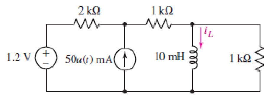
FIGURE 8.86
Expert Solution & Answer
Want to see the full answer?
Check out a sample textbook solution
Students have asked these similar questions
Obtain an expression for i1 as indicated in Fig. 8.85 that is valid for all values
of t.
8. A series RC circuit (Fig. 1 below) with one resistor (R=500 M) and one capacitor
(C=0.5 µF) is connected to an AC voltage supply which supplies a voltage v=100
sin(1000t+309) (from t=0 to t=∞). The initial charge on the capacitor is Qo = 25 µC
and the initial voltage on the capacitor is in the same sense as the AC voltage supply.
Obtain the current for t > 0.
Qo
Figure 1
500 D
0.5 μF
100 V
10 Ω
250
0.01 H
Figure 2
iz
250
Obtain an equation which describes the behavior of iA as labeled in Fig. 8.88
over the range of −1 ms ≤ t ≤ 5 ms.
Chapter 8 Solutions
Loose Leaf for Engineering Circuit Analysis Format: Loose-leaf
Ch. 8.1 - For the circuit in Fig. 8.2, what value of...Ch. 8.1 - Noting carefully how the circuit changes once the...Ch. 8.2 - In a source-free series RC circuit, find the...Ch. 8.3 - Prob. 4PCh. 8.3 - Prob. 5PCh. 8.4 - Prob. 6PCh. 8.4 - Prob. 7PCh. 8.4 - Prob. 8PCh. 8.5 - Evaluate each of the following at t = 0.8: (a)...Ch. 8.6 - For the circuit of Fig. 8.37, find vc(t) at t...
Ch. 8.7 - Prob. 11PCh. 8.7 - The voltage source 60 40u(t) V is in series with...Ch. 8.7 - Prob. 13PCh. 8.8 - Prob. 14PCh. 8.8 - Prob. 15PCh. 8 - A source-free RC circuit has R = 4 k and C = 22 F,...Ch. 8 - A source-free RC circuit has v(0) = 12 V and R =...Ch. 8 - The resistor in the circuit of Fig. 8.51 has been...Ch. 8 - Prob. 4ECh. 8 - Prob. 5ECh. 8 - Prob. 6ECh. 8 - Prob. 7ECh. 8 - Prob. 8ECh. 8 - Prob. 9ECh. 8 - The switch in Fig. 8.56 has been closed for a long...Ch. 8 - For the circuit in Fig. 8.56, find (a) the total...Ch. 8 - Design a capacitor-based circuit that can achieve...Ch. 8 - (a) Graph the function f (t) = 10e2t over the...Ch. 8 - The current i(t) flowing through a 1 k resistor is...Ch. 8 - Radiocarbon dating has a similar exponential time...Ch. 8 - For the circuit of Fig. 8.4, compute the time...Ch. 8 - Design a circuit which will produce a current of 1...Ch. 8 - Prob. 18ECh. 8 - Prob. 19ECh. 8 - Referring to the circuit shown in Fig. 8.11,...Ch. 8 - Prob. 21ECh. 8 - With the assumption that the switch in the circuit...Ch. 8 - The switch in Fig. 8.57 has been closed since...Ch. 8 - The switch in the circuit of Fig. 8.58 has been...Ch. 8 - Assuming the switch initially has been open for a...Ch. 8 - (a) Obtain an expression for v(t), the voltage...Ch. 8 - For the circuit of Fig. 8.61, determine ix, iL,...Ch. 8 - Prob. 28ECh. 8 - Prob. 29ECh. 8 - Prob. 30ECh. 8 - Prob. 31ECh. 8 - (a) Obtain an expression for vx as labeled in the...Ch. 8 - Prob. 33ECh. 8 - Prob. 34ECh. 8 - Prob. 35ECh. 8 - Prob. 36ECh. 8 - Prob. 37ECh. 8 - The switch in Fig. 8.70 is moved from A to B at t...Ch. 8 - Prob. 39ECh. 8 - Prob. 40ECh. 8 - Evaluate the following functions at t = 1, 0, and...Ch. 8 - Prob. 42ECh. 8 - Prob. 43ECh. 8 - Prob. 44ECh. 8 - You can use MATLAB to represent the unit-step...Ch. 8 - With reference to the circuit depicted in Fig....Ch. 8 - For the circuit given in Fig. 8.75, (a) determine...Ch. 8 - Prob. 48ECh. 8 - Prob. 49ECh. 8 - You build a portable solar charging circuit...Ch. 8 - The switch in the circuit of Fig. 8.78 has been...Ch. 8 - The switch in the circuit of Fig. 8.78 has been...Ch. 8 - Prob. 53ECh. 8 - Prob. 54ECh. 8 - Prob. 55ECh. 8 - For the circuit represented in Fig. 8.82, (a)...Ch. 8 - Prob. 58ECh. 8 - Prob. 59ECh. 8 - For the circuit given in Fig. 8.85, (a) determine...Ch. 8 - The circuit depicted in Fig. 8.86 contains two...Ch. 8 - Prob. 62ECh. 8 - Prob. 63ECh. 8 - A series RL circuit has a voltage that steps from...Ch. 8 - For the two-source circuit of Fig. 8.89, note that...Ch. 8 - (a) Obtain an expression for iL as labeled in Fig....Ch. 8 - Obtain an expression for i(t) as labeled in the...Ch. 8 - Obtain an expression for i1 as indicated in Fig....Ch. 8 - Plot the current i(t) in Fig. 8.93 if (a) R = 10 ;...Ch. 8 - A dc motor can be modeled as a series RL circuit...Ch. 8 - Prob. 71ECh. 8 - Prob. 72ECh. 8 - A series RC sequentially switched circuit has R =...Ch. 8 - Refer to the circuit of Fig. 8.95, which contains...Ch. 8 - In the circuit of Fig. 8.95, a 3 mF capacitor is...Ch. 8 - Prob. 78E
Knowledge Booster


Learn more about
Need a deep-dive on the concept behind this application? Look no further. Learn more about this topic, electrical-engineering and related others by exploring similar questions and additional content below.Similar questions
- An LR-series circuit has a variable inductor with the inductance defined by 1 20 1 0 ≤ t 20. Find the current i(t) if the resistance is 0.1 ohm, the impressed voltage is E(t) = 4, and i(0) = 0. i(t) = L(t) 40 T 0 20arrow_forwardFor the two-source circuit of Fig. 8.89, note that one source is always on. (a) Obtain an expression for i(t) valid for all t; (b) determine at what time the energy stored in the inductor reaches 99 percent of its maximum value.arrow_forward8. 1A 7.3.7 Find ve(t) for t> 0 in the circuit given as follows. K 80 0.04 F 17.(1) 400 1Harrow_forward
- Employing step functions as appropriate, describe the voltage waveform graphed in Fig. 8.73. FIGURE 8.73 v (t) V 4 2 3 4 t(s)arrow_forwardFigure 8 showsa resistor inductor capacitor (RLC) circuit. The input to the system is the voltage v(t) and the output of the circuit is the current iz (t). 8 R, i(t) iz(t) v(t) Ve(t) R2 Figure 8 a) Determine differential equations containing i, (t), iz (t) and v. (t) for the appropriate meshes and nodes. b) Assuming zero initial conditions i) derive Laplace transformations of the differential equations found in a) ii) determine the transfer function G(s) = I2(s) VIs where l2(s) = L{i2 (t}} and V(s) = L{v(t}.arrow_forwardThe switch in Fig. 8.73 is moved from A to B at t = 0 after being at A for a long time. This places the two capacitors in series, thus allowing equal and opposite de voltages to be trapped on the capacitors (d) Find vr(t), t > 0. (e) Find i(t). (f) Find vi(t) and v2(t) from i(t) and the initial values. (g) Show that the stored energy at i = 0 plus the total energy dissipated in the 20 kS2 resistor is equal to the energy stored in the capacitors at t = 0arrow_forward
- A series LR circuit has a variable inductor with theinductance L(t) is defined by intervals.Find the current i(t) if the resistance is 0.2 ohms, the voltageapplied is E(t) = 4 volts; knowing that i(0) = 0.arrow_forwardThe switch in Fig. 8.73 is moved from A to B at t = 0 after being at A for along time. This places the two capacitors in series, thus allowing equal andopposite dc voltages to be trapped on the capacitors. (a) Determine v1(0−),v2(0−), and vR(0−). (b) Find v1(0+), v2(0+), and vR(0+). (c) Determine thetime constant of vR(t). (d) Find vR(t), t > 0. (e) Find i(t). ( f ) Find v1(t) andv2(t) from i(t) and the initial values. (g) Show that the stored energy at t = ∞plus the total energy dissipated in the 20 k-resistor is equal to the energystored in the capacitors at t = 0.arrow_forwardConsider the following circuit. In the circuit, A=3, R1= 4N, R2= 4N,and a =5 R2 2F R1 aic(t) A - Au(t) (1 velt) -tic(t) a) Determine the capacitor voltage at t=0 K and b) The expression for V(s) is- s+p Determine K c) Determine the value of v.(t) at t=2 s d) What is the value of the time constant of the circuit for t>0? +arrow_forward
- Question 29 Obtain expressions for both i₁(t) and i(t) as labeled in Fig. 8.66, which are valid for t > 0. iz 80 5 A I FIGURE 8.66 X. t=0 3 Ω m 3 H 20 1Η ele 2 H чеееarrow_forwardFIGURE 8.62 29. Obtain expressions for both i₁(t) and i(t) as labeled in Fig. 8.63, which are valid for t > 0. www 822 5 A FIGURE 8.63 X t=0 iL 3 Ω 3 H ww 2 Ω 1 H or 2 H (4)arrow_forward54. The switch in the circuit of Fig. 8.80, often called a make-before-break switch (since during switching it briefly makes contact with both parts of the circuit to ensure a smooth electrical transition), moves to position b at t = 0 only after being in position a long enough to ensure all initial transients arising from turning on the sources have long since decayed. (a) Determine the power dissi- pated by the 5 2 resistor at t = 0. (b) Determine the power dissipated in the 3 2 resistor at t = 2 ms. SI 10 mA FIGURE 8.80 5ΩΣ 1Ω (c) M 4 V a ↓ +1 t = 0 b 283+UOIR 8 19 nyol 1 mFvc (1) (5) 8 2856 Tudja i(t) 2Ω, 3 Ω W 13/02a offas 164 DAY 08arrow_forward
arrow_back_ios
SEE MORE QUESTIONS
arrow_forward_ios
Recommended textbooks for you
 Introductory Circuit Analysis (13th Edition)Electrical EngineeringISBN:9780133923605Author:Robert L. BoylestadPublisher:PEARSON
 Delmar's Standard Textbook Of ElectricityElectrical EngineeringISBN:9781337900348Author:Stephen L. HermanPublisher:Cengage Learning
 Programmable Logic ControllersElectrical EngineeringISBN:9780073373843Author:Frank D. PetruzellaPublisher:McGraw-Hill Education
 Fundamentals of Electric CircuitsElectrical EngineeringISBN:9780078028229Author:Charles K Alexander, Matthew SadikuPublisher:McGraw-Hill Education
 Electric Circuits. (11th Edition)Electrical EngineeringISBN:9780134746968Author:James W. Nilsson, Susan RiedelPublisher:PEARSON
 Engineering ElectromagneticsElectrical EngineeringISBN:9780078028151Author:Hayt, William H. (william Hart), Jr, BUCK, John A.Publisher:Mcgraw-hill Education,
Introductory Circuit Analysis (13th Edition)
Electrical Engineering
ISBN:9780133923605
Author:Robert L. Boylestad
Publisher:PEARSON
Delmar's Standard Textbook Of Electricity
Electrical Engineering
ISBN:9781337900348
Author:Stephen L. Herman
Publisher:Cengage Learning
Programmable Logic Controllers
Electrical Engineering
ISBN:9780073373843
Author:Frank D. Petruzella
Publisher:McGraw-Hill Education
Fundamentals of Electric Circuits
Electrical Engineering
ISBN:9780078028229
Author:Charles K Alexander, Matthew Sadiku
Publisher:McGraw-Hill Education
Electric Circuits. (11th Edition)
Electrical Engineering
ISBN:9780134746968
Author:James W. Nilsson, Susan Riedel
Publisher:PEARSON
Engineering Electromagnetics
Electrical Engineering
ISBN:9780078028151
Author:Hayt, William H. (william Hart), Jr, BUCK, John A.
Publisher:Mcgraw-hill Education,
ENA 9.2(1)(En)(Alex) Sinusoids & Phasors - Explanation with Example 9.1 ,9.2 & PP 9.2; Author: Electrical Engineering Academy;https://www.youtube.com/watch?v=vX_LLNl-ZpU;License: Standard YouTube License, CC-BY
Electrical Engineering: Ch 10 Alternating Voltages & Phasors (8 of 82) What is a Phasor?; Author: Michel van Biezen;https://www.youtube.com/watch?v=2I1tF3ixNg0;License: Standard Youtube License