
Concept explainers
Videos
Refer to the circuit of Fig. 8.95, which contains a voltage-controlled dependent voltage source in addition to two resistors. (a) Compute the circuit time constant. (b) Obtain an expression for vx valid for all t. (c) Plot the power dissipated in the 4 Ω resistor over the range of six time constants. (d) Repeat parts (a) to (c) if the dependent source is installed in the circuit upside down. (e) Are both circuit configurations “stable”? Explain.
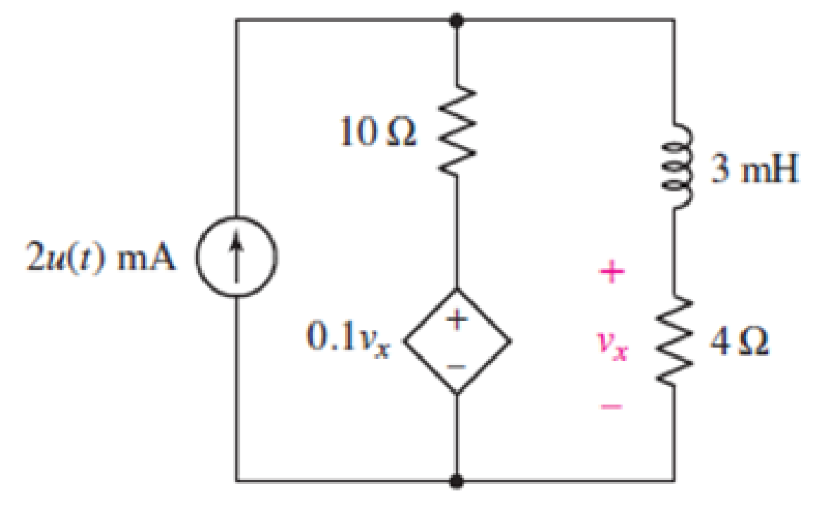
Figures 8.95
(a)
Find the circuit time constant.
Answer to Problem 76E
The time constant of the circuit is
Explanation of Solution
Formula used:
The expression for the resistance of the circuit is as follows:
Here,
The expression for the time constant of circuit is as follows:
Here,
Calculation:
To find equivalent resistance of a circuit the independent current source is replaced by open circuit and
The circuit diagram is redrawn as shown in Figure 1.
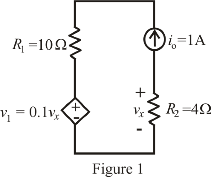
Refer to the redrawn Figure 1:
Apply KVL in mesh 1:
Here,
Substitute
The expression for voltage across the
Here,
Substitute
Substitute
Rearrange for
Substitute
So, the equivalent resistance across inductor is
Substitute
So the time constant of the circuit is
Conclusion:
Thus, the time constant of the circuit is
(b)
Obtain an expression for
Answer to Problem 76E
The expression for the voltage
Explanation of Solution
Formula used:
The expression for the final response of the circuit valid for all
Here,
Calculation:
The unit-step forcing function as a function of time which is zero for all values of its argument less than zero and which is unity for all positive values of its argument.
Here,
The independent current source is:
Substitute
The current through
The
So, the value of the current flowing through the inductor for
The inductor does not allow sudden change in the current.
So,
Therefore, the current flowing in the circuit for
Substitute
So, the current flowing through the
The circuit diagram is redrawn as shown in Figure 2 for
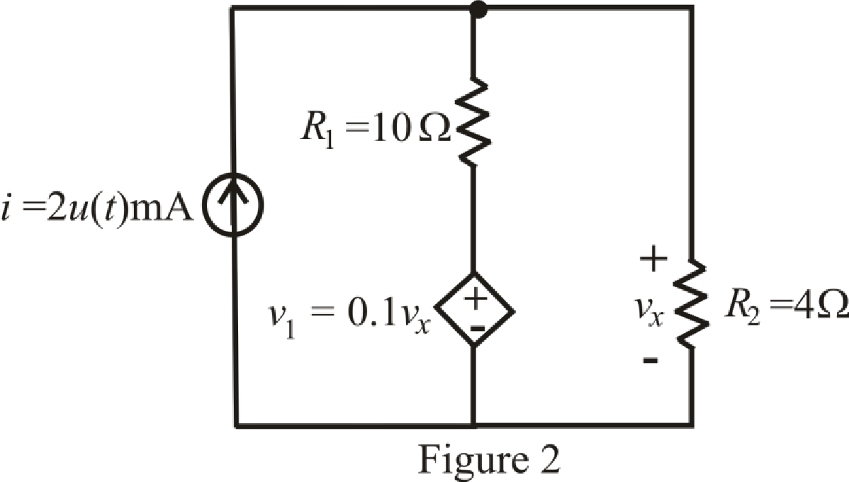
Refer to the redrawn Figure 2:
Apply KCL in the circuit:
Substitute
Rearrange for
The expression for the current flowing through
Here,
Substitute
So, the current flowing through
Substitute
The expression for the voltage across the
Substitute
Conclusion:
Thus, the expression for the voltage
(c)
Plot the power dissipated in the
Explanation of Solution
Given data:
The range of the time is six time constant.
Formula used:
The expression for the power dissipated in the
Here,
Calculation:
Substitute
The time constant of the circuit is
The different value for the power dissipated in the
The graph for power dissipated in the
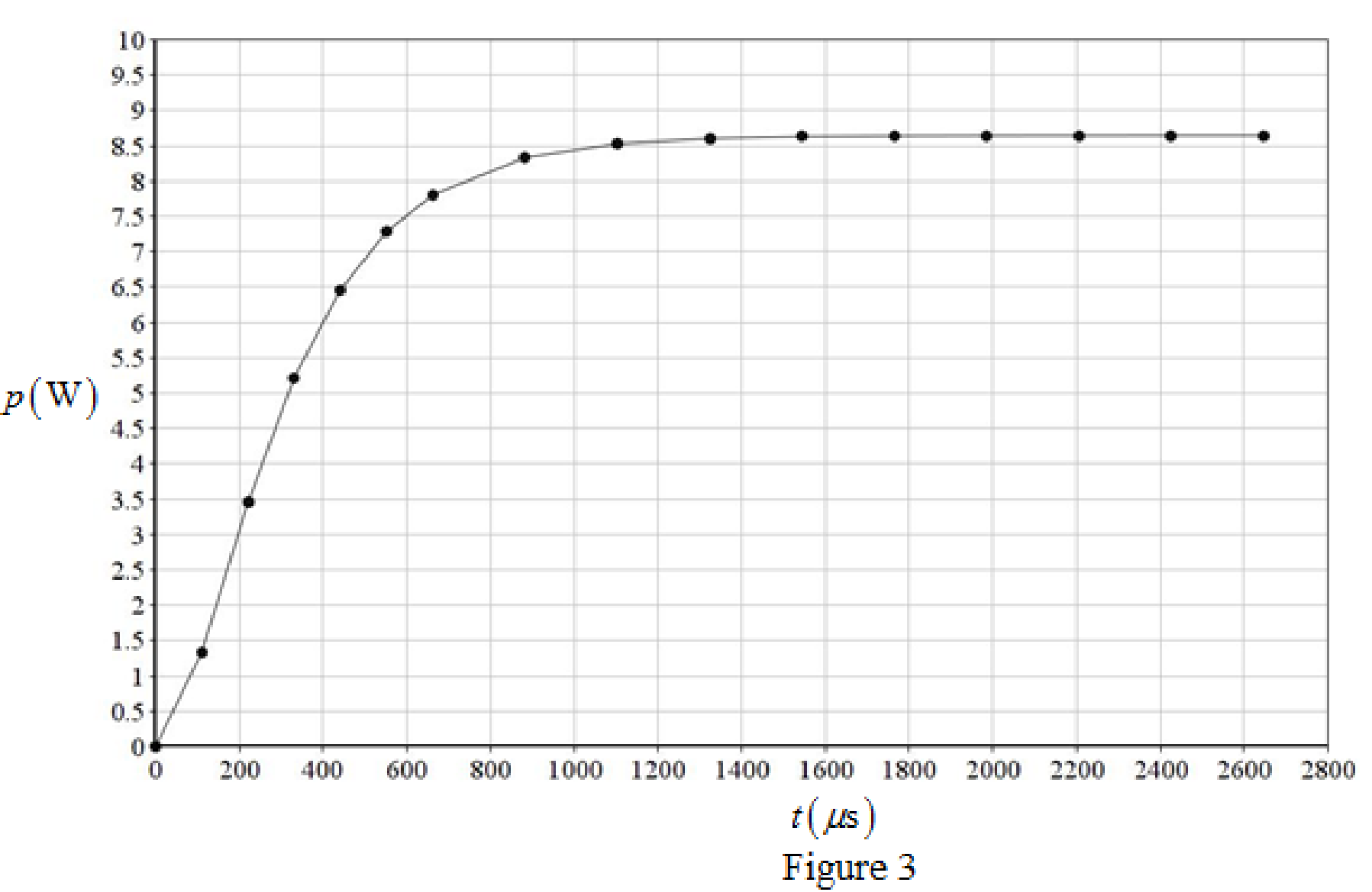
Calculation:
Thus, the graph for power dissipated in the
Conclusion:
(d)
Repeat parts (a) to (c) if the dependent source is installed in the circuit upside down.
Explanation of Solution
Calculation:
To find equivalent resistance of a circuit the independent current source is replaced by open circuit and
The circuit diagram is redrawn as shown in Figure 4:
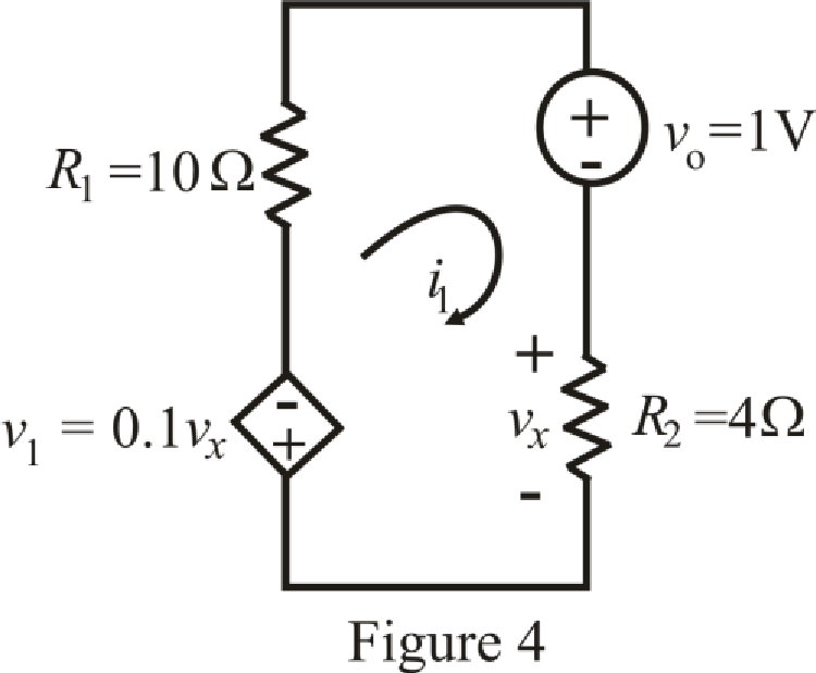
Refer to the redrawn Figure 4:
Apply KVL in mesh 1:
Here,
Substitute
The expression for voltage across the
Here,
Substitute
Substitute
Rearrange for
Substitute
So, the equivalent resistance across inductor is
Substitute
So, the time constant of the circuit is
The unit-step forcing function as a function of time which is zero for all values of its argument less than zero and which is unity for all positive values of its argument.
Here,
The independent voltage source is:
Substitute
The current through
The
So, the value of the current flowing through the inductor for
The inductor does not allow sudden change in the current.
So,
Therefore, the current flowing in the circuit for
Substitute
So, the current flowing through the
The circuit diagram is redrawn as shown in Figure 5 for
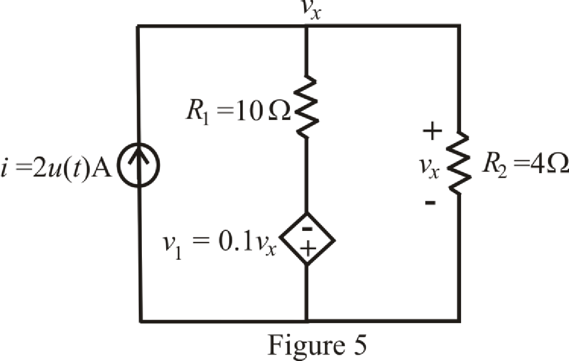
Refer to the redrawn Figure 5:
Apply KCL in the circuit:
Substitute
Rearrange for
The expression for the current flowing through
Here,
Substitute
So, the current flowing through
Substitute
The expression for the voltage across the
Substitute
So, the expression for the voltage
Substitute
The time constant of the circuit is
The different value for the power dissipated in the
The graph for power dissipated in the
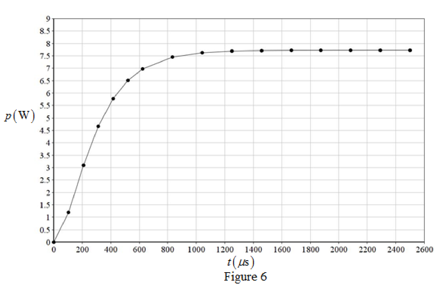
Conclusion:
Thus, the time constant of the circuit is
(e)
Are both circuit configurations “stable”? Explain.
Answer to Problem 76E
Both circuit configurations are “stable”.
Explanation of Solution
Refer to Figure 3 and Figure 6:
The response (output power dissipated in the
So, both circuit configurations “stable”.
Conclusion:
Thus, both circuit configurations are “stable”.
Want to see more full solutions like this?
Chapter 8 Solutions
Loose Leaf for Engineering Circuit Analysis Format: Loose-leaf
Additional Engineering Textbook Solutions
Basic Engineering Circuit Analysis
Electronics Fundamentals: Circuits, Devices & Applications
Electric Circuits (10th Edition)
Electric Circuits. (11th Edition)
Fundamentals of Applied Electromagnetics (7th Edition)
Principles and Applications of Electrical Engineering


- The electricity supplied by a typical wall socket is driven by an alternating current. This alternating current gives rise to a voltage that oscillates (peak-to-peak) 60 times each second and ranges from −120V to +120V . Find a function, V (t), which models the voltage as a function of time and fix any constants involved based on the information given. (You may choose the value of V (t) at t = 0.)arrow_forward30 45 N 50 E A B D N 45 30 N 50 E 2. 100 m (a) Figure 8.44 N 40W N 40 Warrow_forwardQuestion 8. 12V in R₁ A R₁ 5 V C R₂2 w R₂ 4 Consider the circuit below, where the capacitor is uncharged, and the switch is open. The different elements of the circuit have the following values: R₁ = 22, R₂ = 22, R3 = 422, R₁ = 82, R₁ = 82 and C = 10 µF. What is the current I₁ in the circuit when the switch is moved to position 1? Enter your answer, in Amps, in the box below. The answer is acceptable within a tolerance of 0.1 A. h₁: R3 After a long time that the switch has been closed, what is the voltage Vc across the capacitor? Enter your answer, in Volts, in the box below. The answer is acceptable within a tolerance of 0.1 V. Vc:arrow_forward
- Compute the Values: (show solutions)arrow_forwardConsider a model (Electric RLC series Circuit) find the steady state current in a circuit using the following data L = 1.2 henry, 20 R = 12 ohms C == x 10- farad, E(t)12000 sin25t volt Write the detail of your work.arrow_forwardelectrical circuit show complete solutionarrow_forward
- 41. Using loop current method find the current I, and I shown in Fig. 7. [U.P. Technical Univ. Electrical Engineering Second Semester 2005-06] 20 [Ans. A and A] 33 11 HILL 10 V 202 www 11 (652 Fig. 7 30 www 502 www 2Varrow_forwardAssuming an op amp gain of 1000 and Is = 10-17 A for D1, plot the input/output characteristic of the precision rectifier shown in Fig.8.69. Vino Y Vout D1 1 k2arrow_forwardA 12 volt battery is connected to a simple series circuit where the inductance is 1/2 henrio and the resistance is 10 ohms. Determine the current if the initial current is 0. topic: ORDINARY DIFFERENTIAL EQUATIONSarrow_forward
- 7.-In a circuit with a 24 V supply, a 6 µF capacitor and a 650 Ω. Determine: (a) The time constant. b) The initial current at 0.04 seconds in the resistor. 8.- Determine the time constant in a circuit inside a remote control with a supply of 9 V, if it is connected to a capacitor of 6 µF and a resistor of 400Ω7.- In a circuit with a power supply of 24 V, a capacitor of 6 µF and a resistor of 650 Ω. Determine: (a) The time constant. b) The initial current at 0.04 seconds in the resistance. I hope you can help me, thank you very much. Thank youarrow_forward1. For the circuit , find vo for t≥0.2. Show that your solution for vo is consistent with the solution for ioarrow_forward8. A 62.5-µf capacitor is connected in series with a 200,000-ohm resistor and to a 250-volt d-c source. (a) Write the expression for the charging current following the closing of the switch. (b) What is the initial charging current? (c) Calculate the time constant and the charging current at t = t. (d) What will be the initial rate of current change?arrow_forward
 Introductory Circuit Analysis (13th Edition)Electrical EngineeringISBN:9780133923605Author:Robert L. BoylestadPublisher:PEARSON
 Delmar's Standard Textbook Of ElectricityElectrical EngineeringISBN:9781337900348Author:Stephen L. HermanPublisher:Cengage Learning
 Programmable Logic ControllersElectrical EngineeringISBN:9780073373843Author:Frank D. PetruzellaPublisher:McGraw-Hill Education
 Fundamentals of Electric CircuitsElectrical EngineeringISBN:9780078028229Author:Charles K Alexander, Matthew SadikuPublisher:McGraw-Hill Education
 Electric Circuits. (11th Edition)Electrical EngineeringISBN:9780134746968Author:James W. Nilsson, Susan RiedelPublisher:PEARSON
 Engineering ElectromagneticsElectrical EngineeringISBN:9780078028151Author:Hayt, William H. (william Hart), Jr, BUCK, John A.Publisher:Mcgraw-hill Education,