
Videos
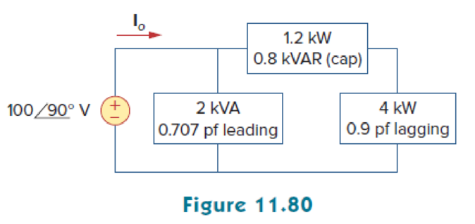
Given the circuit in Fig. 11.80, find Io and the overall complex power supplied.
Calculate the current
Answer to Problem 61P
The current
Explanation of Solution
Given data:
Refer to Figure 11.80 in the textbook.
The current
For load A,
The apparent power
The power factor
For load B,
The real power
The real power
For load C,
The real power
The power factor
Formula used:
Write the expression to find the complex power.
Here,
Write the expression to find the power factor
Here,
Write the expression to find the real power.
Write the expression to find the reactive power.
Write the expression to find the output voltage.
Calculation:
The given Figure 11.80 is redrawn as shown in Figure 1.
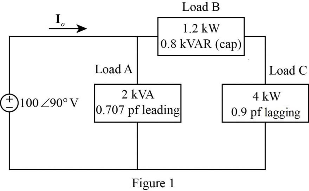
For load A:
Substitute
Substitute
Substitute
Substitute
As the power factor is leading, the load is capacitive. Therefore, the equation becomes,
For load B:
Substitute
As the load is capacitive, the power factor is leading. Therefore, the equation becomes,
For load C:
Substitute
Substitute
Rearrange the equation as follows,
Substitute
Substitute
In Figure 1, the load B and load C are connected in series. Therefore,
Substitute
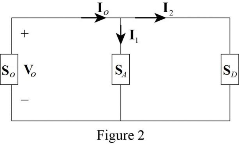
The modified Figure is shown in Figure 2.
Substitute
Substitute
Apply Kirchhoff’s current law in Figure 2 to find the current
Substitute
Convert the equation from rectangular to polar form.
The overall complex power supplied by the source is,
Substitute
Conclusion:
Thus, the current
Want to see more full solutions like this?
Chapter 11 Solutions
Fundamentals of Electric Circuits


- For the circuit in fig .11.82 A. Write the mathematical expressions for the current IL and the voltage Vl following the closing of the switch. B. Sketch the waveform of iL and VL for the entire period from initial value to steady-state level.arrow_forwardA 5-ohm resistor is connected in series with a 25 micro-farad capacitor. A source voltage of 158 volts, 50 Hz supplies the combination. Determine the following: d. Real power supplied by the source e. Reactive power supplied by the source f. Apparent power of the circuit g. Power factor of the entire circuitarrow_forwardA 5-ohm resistor is connected in series with a 25 micro-farad capacitor. A source voltage of 158 volts, 50 Hz supplies the combination. Determine the following: a. Circulating current b. Voltage across the resistor c. Voltage across the capacitor d. Real power supplied by the source e. Reactive power supplied by the source f. Apparent power of the circuit g. Power factor of the entire circuitarrow_forward
- For the circuit of Fig.11.78 composed of standard values: A. Determine the time constant. B. Write the mathematical expression for the current It after the switch is closed C. Repeat part (b) for VL and VR D. Determine il and VL at one three- and five-time constants. E. Sketch the waveforms of iL,VL and VR.arrow_forwardQ2) A three phase load (motor) draws 30 kW when connected to 440 V rms, 50 Hz line if the power factor is 0.85 lagging, Determine: a) The line current drawn by the motor. b) The KVAR rating of the three capacitors - connected in parallel with the motor that will raise the power factor to 0.95 lagging, and c) The capacitance of each capacitor.arrow_forwardA resistor of 10ohm and an inductor of 0.2 henry are connected in series and given a supply of 230 V, 50 Hz, then (i) Inductive reactance (ii) Impedance (iii) Current (iv) Power factor (v) True power (vi) Reactive power and (vii) find the apparent powerarrow_forward
- 1. An alternating voltage is given by V=230sin314t.Calculate i)frequency,ii)maximum value,iii)average value,iv)RMS valućarrow_forwardThree coils each having resistance of 12 Q and the phase current 18 A are connected in delta across 415V, 60 Hz supply. Then total power consumed in watts is,arrow_forwardA 1500 kvA, 3Φ star-connected alternator, 50 Hz,2300 V alternator has a resistance between each pair of terminals as measured by direct currents is 0.16 ohm. Assume that the effective resistance is 1.5 times the ohmic value. A field current of 70 A produces a short-circuit current equal to full load current of 376 A in each line. The same field current produces an emf of 700 V on open circuit. Determine the synchronous reactance of the machine and its full load voltage regulation at 0.8 power factor lagging. [Ans. VR = 22.8 %]arrow_forward
- A single phase motor is connected 400 V, 50 Hz supply takes 54 A at a power factor of 0.6 lagging. Calculate the capacitance required in parallel to the motor to rise the power factor as 0.85 lagging.arrow_forward1. What should be the kVA rating of a capacitor which would raise the power factor of load of 100 kW from 0-5 lagging to 0-9 lagging ? [125 kVA]arrow_forwardA resistance of 20 ohm and a coil of inductance 31.8 mH and negligible resistance are connected in parallel across 230V, 50 Hz supply. Find the A) Line Current B) Power Factor C) Power consumed by the circuitarrow_forward
 Introductory Circuit Analysis (13th Edition)Electrical EngineeringISBN:9780133923605Author:Robert L. BoylestadPublisher:PEARSON
 Delmar's Standard Textbook Of ElectricityElectrical EngineeringISBN:9781337900348Author:Stephen L. HermanPublisher:Cengage Learning
 Programmable Logic ControllersElectrical EngineeringISBN:9780073373843Author:Frank D. PetruzellaPublisher:McGraw-Hill Education
 Fundamentals of Electric CircuitsElectrical EngineeringISBN:9780078028229Author:Charles K Alexander, Matthew SadikuPublisher:McGraw-Hill Education
 Electric Circuits. (11th Edition)Electrical EngineeringISBN:9780134746968Author:James W. Nilsson, Susan RiedelPublisher:PEARSON
 Engineering ElectromagneticsElectrical EngineeringISBN:9780078028151Author:Hayt, William H. (william Hart), Jr, BUCK, John A.Publisher:Mcgraw-hill Education,