
Fundamentals of Electric Circuits
6th Edition
ISBN: 9780078028229
Author: Charles K Alexander, Matthew Sadiku
Publisher: McGraw-Hill Education
expand_more
expand_more
format_list_bulleted
Concept explainers
Videos
Textbook Question
Chapter 11, Problem 92CP
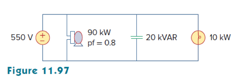
As shown in Fig. 11.97, a 550-V feeder line supplies an industrial plant consisting of a motor drawing 90 kW at 0.8 pf (inductive), a capacitor with a rating of 20 kVAR, and lighting drawing 10 kW.
- (a) Calculate the total reactive power and apparent power absorbed by the plant.
- (b) Determine the overall pf.
- (c) Find the magnitude of the current in the feeder line.
Expert Solution & Answer
Want to see the full answer?
Check out a sample textbook solution
Students have asked these similar questions
1. A motor load consists of a resistance of 6 Ohms in series with an inductance of 12 mH. Assume 120Vac, 60 Hz supply.
a. What is the complex impedance of the load?
b. What is the ac current through this load?
c. What is theta, the angle between voltage and current through this load?
d. What is the power factor?
e. What capacitance should be added in parallel with this load to correct the power factor to 1?
f. What is the current from the supply when the power factor is corrected?
A 5-ohm resistor is connected in series with a 25 micro-farad capacitor. A source voltage of
158 volts, 50 Hz supplies the combination. Determine the following:
a. Circulating current
b. Voltage across the resistor
c. Voltage across the capacitor
d. Real power supplied by the source
e. Reactive power supplied by the source
f. Apparent power of the circuit
g. Power factor of the entire circuit
A capacitor drawing 4 kvar is placed in parallel with the electro-magnet that draws 3 kW of active power and 4 kvar of reactive power.. a. Calculate the new value of apparent power b. What is the new value of reactive power? c. What is the value of active power? d. What is the new power factor?
Chapter 11 Solutions
Fundamentals of Electric Circuits
Ch. 11.2 - Calculate the instantaneous power and average...Ch. 11.2 - A current A flows through an impedance Find the...Ch. 11.2 - In the circuit of Fig. 11.4, calculate the average...Ch. 11.2 - Calculate the average power absorbed by each of...Ch. 11.3 - For the circuit shown in Fig. 11.10, find the load...Ch. 11.3 - In Fig. 11.12, the resistor RL is adjusted until...Ch. 11.4 - Find the rms value of the current waveform of Fig....Ch. 11.4 - Find the rms value of the full-wave rectified sine...Ch. 11.5 - Prob. 9PPCh. 11.5 - Prob. 10PP
Ch. 11.6 - For a load, Determine: (a) the complex and...Ch. 11.6 - A sinusoidal source supplies 100 kVAR reactive...Ch. 11.7 - In the circuit in Fig. 11.25, the 60- resistor...Ch. 11.7 - Two loads connected in parallel are respectively 3...Ch. 11.8 - Find the value of parallel capacitance needed to...Ch. 11.9 - For the circuit in Fig. 11.33, find the wattmeter...Ch. 11.9 - The monthly reading of a paper mills meter is as...Ch. 11.9 - An 500-kW induction furnace at 0.88 power factor...Ch. 11 - The average power absorbed by an inductor is zero,...Ch. 11 - The Thevenin impedance of a network seen from the...Ch. 11 - The amplitude of the voltage available in the...Ch. 11 - If the load impedance is 20 j20, the power factor...Ch. 11 - A quantity that contains all the power information...Ch. 11 - Reactive power is measured in: (a) watts (b) VA...Ch. 11 - In the power triangle shown in Fig. 11.34(a), the...Ch. 11 - For the power triangle in Fig. 11.34(b), the...Ch. 11 - A source is connected to three loads Z1, Z2, and...Ch. 11 - The instrument for measuring average power is the:...Ch. 11 - If v(t) = 160 cos 50t V and i(t) = 33 sin (50t ...Ch. 11 - Given the circuit in Fig. 11.35, find the average...Ch. 11 - A load consists of a 60- resistor in parallel with...Ch. 11 - Using Fig. 11.36, design a problem to help other...Ch. 11 - ssuming that vs = 8 cos(2t 40) V in the circuit...Ch. 11 - For the circuit in Fig. 11.38, is = 6 cos 103t A....Ch. 11 - Given the circuit of Fig. 11.39, find the average...Ch. 11 - In the circuit of Fig. 11.40, determine the...Ch. 11 - For the op amp circuit in Fig. 11.41, Find the...Ch. 11 - In the op amp circuit in Fig. 11.42, find the...Ch. 11 - For the network in Fig. 11.43, assume that the...Ch. 11 - For the circuit shown in Fig. 11.44, determine the...Ch. 11 - The Thevenin impedance of a source is ZTh = 120 +...Ch. 11 - Using Fig. 11.45, design a problem to help other...Ch. 11 - In the circuit of Fig. 11.46, find the value of ZL...Ch. 11 - For the circuit in Fig. 11.47, find the value of...Ch. 11 - Calculate the value of ZL in the circuit of Fig....Ch. 11 - Find the value of ZL in the circuit of Fig. 11.49...Ch. 11 - The variable resistor R in the circuit of Fig....Ch. 11 - The load resistance RL in Fig. 11.51 is adjusted...Ch. 11 - Assuming that the load impedance is to be purely...Ch. 11 - Find the rms value of the offset sine wave shown...Ch. 11 - Using Fig. 11.54, design a problem to help other...Ch. 11 - Determine the rms value of the waveform in Fig....Ch. 11 - Find the rms value of the signal shown in Fig....Ch. 11 - Find the effective value of the voltage waveform...Ch. 11 - Calculate the rms value of the current waveform of...Ch. 11 - Find the rms value of the voltage waveform of Fig,...Ch. 11 - Calculate the effective value of the current...Ch. 11 - Compute the rms value of the waveform depicted in...Ch. 11 - Find the rms value of the signal shown in Fig....Ch. 11 - Obtain the rms value of the current waveform shown...Ch. 11 - Determine the rms value for the waveform in Fig....Ch. 11 - Find the effective value f(t) defined in Fig....Ch. 11 - One cycle of a periodic voltage waveform is...Ch. 11 - Calculate the rms value for each of the following...Ch. 11 - Design a problem to help other students better...Ch. 11 - For the power system in Fig. 11.67, find: (a) the...Ch. 11 - An ac motor with impedance ZL = 2 + j 1.2 is...Ch. 11 - Design a problem to help other students better...Ch. 11 - Obtain the power factor for each of the circuits...Ch. 11 - A 110-V rms, 60-Hz source is applied to a load...Ch. 11 - Design a problem to help other students understand...Ch. 11 - Find the complex power delivered by vs to the...Ch. 11 - The voltage across a load and the current through...Ch. 11 - For the following voltage and current phasors,...Ch. 11 - For each of the following cases, find the complex...Ch. 11 - Determine the complex power for the following...Ch. 11 - Find the complex power for the following cases:...Ch. 11 - Obtain the overall impedance for the following...Ch. 11 - For the entire circuit in Fig. 11.70, calculate:...Ch. 11 - In the circuit of Fig. 11.71, device A receives 2...Ch. 11 - In the circuit of the Fig. 11.72, load A receives...Ch. 11 - For the network in Fig. 11.73, find the complex...Ch. 11 - Using Fig. 11.74, design a problem to help other...Ch. 11 - Obtain the complex power delivered by the source...Ch. 11 - For the circuit in Fig. 11.76, find the average,...Ch. 11 - Obtain the complex power delivered to the 10-k...Ch. 11 - Calculate the reactive power in the inductor and...Ch. 11 - For the circuit in Fig. 11.79, find Vo and the...Ch. 11 - Given the circuit in Fig. 11.80, find Io and the...Ch. 11 - For the circuit in Fig. 11.81, find Vs.Ch. 11 - Find Io in the circuit of Fig. 11.82. Figure 11.82Ch. 11 - Determine Is in the circuit of Fig. 11.83, if the...Ch. 11 - In the op amp circuit of Fig. 11.84, vs = 4 cos...Ch. 11 - Obtain the average power absorbed by the 10-...Ch. 11 - For the op amp circuit in Fig. 11.86, calculate:...Ch. 11 - Compute the complex power supplied by the current...Ch. 11 - Refer to the circuit shown in Fig. 11.88. (a) What...Ch. 11 - Design a problem to help other students better...Ch. 11 - Three loads are connected in parallel to a rms...Ch. 11 - Two loads connected in parallel draw a total of...Ch. 11 - A 240-V rms 60-Hz supply serves a load that is 10...Ch. 11 - A 120-V rms 60-Hz source supplies two loads...Ch. 11 - Consider the power system shown in Fig. 11.90....Ch. 11 - Obtain the wattmeter reading of the circuit in...Ch. 11 - What is the reading of the wattmeter in the...Ch. 11 - Find the wattmeter reading of the circuit shown in...Ch. 11 - Determine the wattmeter reading of the circuit in...Ch. 11 - The circuit of Fig. 11.95 portrays a wattmeter...Ch. 11 - Design a problem to help other students better...Ch. 11 - A 240-V rms 60-Hz source supplies a parallel...Ch. 11 - Oscilloscope measurements indicate that the peak...Ch. 11 - A consumer has an annual consumption of 1200 MWh...Ch. 11 - A regular household system of a single-phase...Ch. 11 - A transmitter delivers maximum power to an antenna...Ch. 11 - In a TV transmitter, a series circuit has an...Ch. 11 - A certain electronic circuit is connected to a...Ch. 11 - An industrial heater has a nameplate that reads:...Ch. 11 - A 2000-kW turbine-generator of 0.85 power factor...Ch. 11 - The nameplate of an electric motor has the...Ch. 11 - As shown in Fig. 11.97, a 550-V feeder line...Ch. 11 - A factory has the following four major loads: A...Ch. 11 - A 1-MVA substation operates at full load at 0.7...Ch. 11 - Prob. 95CPCh. 11 - A power amplifier has an output impedance of 40 +...Ch. 11 - A power transmission system is modeled as shown in...
Knowledge Booster


Learn more about
Need a deep-dive on the concept behind this application? Look no further. Learn more about this topic, electrical-engineering and related others by exploring similar questions and additional content below.Similar questions
- 1.1) Which of the following descriptions IS NOT correct for loads in power systems? A. The purely resistive load absorbs the real power from the power grid B. The purely inductive load absorbs the positive reactive power from the power grid C. The purely capacitive load absorbs the positive reactive power from the power grid. D. The average value of the instantaneous power through loads is equal to its real power. 1.2) In an ac circuit, power factor correction or improvement is achieved by A. Connecting a resistor in parallel with the inductive load B. Connecting an inductor in parallel with the inductive load C. Connecting a capacitor in parallel with the inductive load 1.3)A balanced delta-load can be converted to an equivalent balanced wve- load by dividing the delta-load impedance by A. square root of 3 В.3 C. 1/3arrow_forwardA 230V, 50HZ single-phase alternator supplies a fully-loaded 15kW induction motor. The full-load efficiency of the motor is 80% and the power factor of this load is 0.75. Determine (i) The real power. The apparent power. (ii) The reactive power. (iv) The power rating of the capacitor required to adjust the power factor to 0.95.arrow_forwardAn induction motor draws 45 kW at a 73% power factor from a 16 AC line. a) What is the phase angle? b) What is the reactive power? c) What is the apparent power? A E A/ d) How many standard 15 kVAR and/or 25 kVAR capacitors are needed to improve the power factor without producing a leading power factor? A 15 kV AR capacitor(s) A/25 kVAR capacitor(s) e) What is the new power factor (round to three decimal spots)?arrow_forward
- A 5-ohm resistor is connected in series with a 25 micro-farad capacitor. A source voltage of158 volts, 50 Hz supplies the combination. Determine the following: e. Reactive power supplied by the sourcef. Apparent power of the circuitg. Power factor of the entire circuitarrow_forward1. What should be the kVA rating of a capacitor which would raise the power factor of load of 100 kW from 0-5 lagging to 0-9 lagging ? [125 kVA]arrow_forward5. A 240-V rms 60-Hz source supplies a parallel combination of a 5-kW heater and a 30-kVA induction motor whose power factor is 0.82. Determine: (a) the system apparent power (b) the system reactive power (c) the kVA rating of a capacitor required to adjust the system power factor to 0.9 lagging (d) the value of the capacitor required.arrow_forward
- If the inductance and capacitance of power system are respectively 1 H and 0.01 uF and the instantaneous value of intrupt current is 10 A, what is the voltage across the circuit breaker contact? Ans=100 kvarrow_forwardA 5-ohm resistor is connected in series with a 25 micro-farad capacitor. A source voltage of 158 volts, 50 Hz supplies the combination. Determine the following: d. Real power supplied by the source e. Reactive power supplied by the source f. Apparent power of the circuit g. Power factor of the entire circuitarrow_forwardThe following data relate to a 50 Hz generator. e.m.f. to neutral = 7.5 kV (rms) Reactance of generator and connected system = 5Ω Distributed capacitance to neutral = 0.02 µF (Resistance negligible) Calculate the following: (1) Maximum voltage across the contacts of circuit breaker when it breaks a short circuit current at zero current. (2) Frequency of the transient oscillation.arrow_forward
- A 3-Φ, 5 KW induction motor has a p.f of 0.75 lagging. A bank of capacitors is connected in delta across the supply terminals and p.f raised to 0.9 lagging. Determine the KVAR rating of the capacitor connected in each phase. Also comment on the type of supplied KVAR, Whether it is unity, leading or lagging.arrow_forwardThe average load of a dairy plant at 11 kV, 50 Hz is 950 kW at 80 percent power factor but the maximum contract load of plant is 1200 kW. As per local electricity regulating authorities norms, consumer must keep the power factor of 95 percent to avoid any poor power factor penalty. Determine the following (i) Rating of capacitor bank (in kVAr) (ii) The capacitance of the capacitor bank (in micro Farad) (iii) Explain why the power factor becomes low and how the capacitor bank will assists to improve the power factor?arrow_forwardThree loads are connected in parallel to a 240-V, 60 Hz supply. Load 1 is composed of three 600-W heaters, Load 2 is a 3 HP, inductive motor with an efficiency of 90% and a p.f. of 0.88, while Load 3 has an impedance of 12-j16 ohms. Determine the following: a) The apparent power of each load b) The Total Power, Total Reactive Power, Total Apparent Power, Power Factor c) The source currentarrow_forward
arrow_back_ios
SEE MORE QUESTIONS
arrow_forward_ios
Recommended textbooks for you
 Power System Analysis and Design (MindTap Course ...Electrical EngineeringISBN:9781305632134Author:J. Duncan Glover, Thomas Overbye, Mulukutla S. SarmaPublisher:Cengage Learning
Power System Analysis and Design (MindTap Course ...
Electrical Engineering
ISBN:9781305632134
Author:J. Duncan Glover, Thomas Overbye, Mulukutla S. Sarma
Publisher:Cengage Learning
Types of Energy for Kids - Renewable and Non-Renewable Energies; Author: Smile and Learn - English;https://www.youtube.com/watch?v=w16-Uems2Qo;License: Standard Youtube License