
Concept explainers
Videos
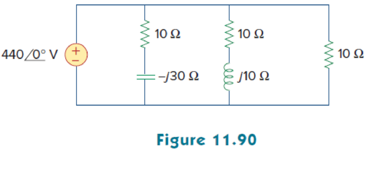
Consider the power system shown in Fig. 11.90. Calculate:
- (a) the total complex power
- (b) the power factor
- (c) the parallel capacitance necessary to establish a unity power factor
(a)
Calculate the complex power of the circuit shown in Figure 11.90.
Answer to Problem 75P
The total complex power for the given circuit is
Explanation of Solution
Given data:
Refer to Figure 11.90 in the textbook.
The voltage
The capacitance C is
The inductance L is
Formula used:
Write the expression to find the complex power.
Here,
Write the expression to find the complex power.
Here,
Calculation:
Refer to figure 11.90 in the textbook.
Consider the impedance
Consider the impedance
Consider the impedance
Substitute
Substitute
Substitute
The total complex power is,
Substitute
Comparing the above equation with equation (1).
Hence, the total complex power is,
Conclusion:
Thus, the total complex power for the given circuit is
(b)
Find the power factor for the given circuit.
Answer to Problem 75P
The power factor for the given circuit is
Explanation of Solution
Given data:
The voltage
From Part (a),
The real power and the reactive power is,
Formula used:
Write the expression to find the power factor
Here,
Write the expression for phase angle
Calculation:
Substitute
Substitute
Conclusion:
Thus, the power factor for the given circuit is
(c)
Find the parallel capacitance value required to establish a unity power factor.
Answer to Problem 75P
The value of capacitance is
Explanation of Solution
Given data:
The voltage
Formula used:
Write the expression to find the value of the capacitance.
Here,
Calculation:
Consider the frequency is
From equation (3), the reactive power is,
Substitute
Simplify the equation as follows,
Conclusion:
Thus, the value of capacitance is
Want to see more full solutions like this?
Chapter 11 Solutions
Fundamentals of Electric Circuits


- Electrical Engineering Determine the load (a)rms voltage and (b) average load current when the conduction angle is 30 degrees. Consider One decimal place for your final answers D, De 110V, 50 Hz A 0. D, wwarrow_forwardCalculate what is required for the circuit below knowing that: a) The power factor b) The average power released by the strong one. c) The reactive power.arrow_forwardA 102 resistor, a 100µF capacitor and an inductor of 0.15H are connected in series to a supply at 240V, 50Hz. Calculate a. the impedance b. the current flowing c. the p.d. across each component d. the overall power factor, and e. the power taken.arrow_forward
- A capacitor drawing 4 kvar is placed in parallel with the electro-magnet that draws 3 kW of active power and 4 kvar of reactive power.. a. Calculate the new value of apparent power b. What is the new value of reactive power? c. What is the value of active power? d. What is the new power factor?arrow_forward5. A voltage e(t) = 100 sin 314 t is applied to a series circuit consisting of 10 ohmsresistance, 0.0318 henry inductance and a capacitance of 63.6 μF. Determine:a. Expression for i(t)b. Phase angle between voltage and currentc. Power factord. Active power consumede. Peak value of pulsating energyarrow_forwardFor an inductive load, the real (active) power is P = 30 W and the reactive power is Q=30 VAR. Calculate the apparent power, S, in VA. Your Answer: Answer unitsarrow_forward
- 1. Discuss the following term in reactive circuit? a) Real power b) Apparent power c) Power factorarrow_forwardThe circuit in the figure below is fed by an alternating voltage with the rms value U. The resistor R consumes the power P. The reactance of the capacitor is X and it consumes Qreak. a) Calculate the reactance X b) Calculate the current c) Calculate the voltage U d) Calculate impedance a Zarrow_forwardUsing the Illustration below. Compute the total impedance (Z), the total current (I), the voltage drop across R. the voltage drop across ??, the voltage drop across ??, the true or useful power (P), the reactive power (Q) and the apparent power (S). (Answer it with a complete solution)arrow_forward
- A coil has a resistance of 30Ω and an inductance of 0.5H . If the current flowing through the coil is 4A. What will be the rms value of the supply voltage (Vs) if its frequency is 60Hz. Using Multisim software to verify this calculated result.arrow_forwardDetermine the total complex, apparent, average, and reactive power. Sketch the power trianglearrow_forwardTwo equal voltages are out of phase with respect to each other by 90 electrical degrees. If the resultant is 311 Volts, what is RMS value of each one?-write legibly-show the complete solutionarrow_forward
 Introductory Circuit Analysis (13th Edition)Electrical EngineeringISBN:9780133923605Author:Robert L. BoylestadPublisher:PEARSON
 Delmar's Standard Textbook Of ElectricityElectrical EngineeringISBN:9781337900348Author:Stephen L. HermanPublisher:Cengage Learning
 Programmable Logic ControllersElectrical EngineeringISBN:9780073373843Author:Frank D. PetruzellaPublisher:McGraw-Hill Education
 Fundamentals of Electric CircuitsElectrical EngineeringISBN:9780078028229Author:Charles K Alexander, Matthew SadikuPublisher:McGraw-Hill Education
 Electric Circuits. (11th Edition)Electrical EngineeringISBN:9780134746968Author:James W. Nilsson, Susan RiedelPublisher:PEARSON
 Engineering ElectromagneticsElectrical EngineeringISBN:9780078028151Author:Hayt, William H. (william Hart), Jr, BUCK, John A.Publisher:Mcgraw-hill Education,