
Fundamentals of Electric Circuits
6th Edition
ISBN: 9780078028229
Author: Charles K Alexander, Matthew Sadiku
Publisher: McGraw-Hill Education
expand_more
expand_more
format_list_bulleted
Videos
Textbook Question
Chapter 16, Problem 15P
For the circuit in Fig. 16.38. calculate the value of R needed to have a critically damped response.
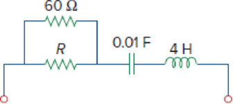
Figure 16.38
Expert Solution & Answer
Want to see the full answer?
Check out a sample textbook solution
Students have asked these similar questions
Considering the system shown below:
R(s)
(s+a) (s+b)
1
S
PID controller
Plant
G(s)
G(s)
a. Set-up the equations and find the value of b and gain K.
b.
Plot the root locus.
K
C(s)
This allows
E ELECTRICAL
mple 3.8:
Consider the circuit in Fig. 16.12(a). Find the
value of the voltage
across the capacitor assuming that the value of vs(t) = 10u(t) V and
assume that at t = 0, -1 A flows through the inductor and +5 V is
across the capacitor.
19 2
EPARTM
%s (1)
ww
rell
(a)
5 H
0.1 F
INEERING
in with th
Problem 16.024 - Current through inductor
The switch in the given circuit has been closed for a long time but is opened at t= 0. Determine (t) for t> 0. Assume v₁ = 40 V.
i(t)
H
m
Vi
(+
F
=
292
ww
t=0
The value of (t) = AeBt C(Dt-E)u(t) A
where A
B=
C = (Click to select) D =
and E=
Chapter 16 Solutions
Fundamentals of Electric Circuits
Ch. 16.2 - Determine vo(t) in the circuit of Fig. 16.6,...Ch. 16.2 - Prob. 2PPCh. 16.2 - Prob. 3PPCh. 16.3 - For the circuit shown in Fig. 16.12 with the same...Ch. 16.3 - Prob. 5PPCh. 16.3 - The initial energy in the circuit of Fig. 16.17 is...Ch. 16.4 - Prob. 7PPCh. 16.4 - Prob. 8PPCh. 16.4 - Prob. 9PPCh. 16.5 - Obtain the state variable model for the circuit...
Ch. 16.5 - Prob. 11PPCh. 16.5 - Prob. 12PPCh. 16.6 - For what value of is the circuit in Fig. 16.29...Ch. 16.6 - Prob. 14PPCh. 16.6 - Prob. 15PPCh. 16.6 - Synthesize the function Vo(s)Vin=2ss2+6s+10 using...Ch. 16 - Prob. 1RQCh. 16 - The current through an RL series circuit with...Ch. 16 - Prob. 3RQCh. 16 - Prob. 4RQCh. 16 - Prob. 5RQCh. 16 - Prob. 6RQCh. 16 - Prob. 7RQCh. 16 - Prob. 8RQCh. 16 - Prob. 9RQCh. 16 - Prob. 10RQCh. 16 - The current in an RLC circuit is described by...Ch. 16 - The differential equation that describes the...Ch. 16 - Prob. 3PCh. 16 - If R = 20 , L = 0.6 H, what value of C will make...Ch. 16 - The responses of a series RLC circuit are vc(t) =...Ch. 16 - Prob. 6PCh. 16 - Prob. 7PCh. 16 - Prob. 8PCh. 16 - Prob. 9PCh. 16 - The step responses of a series RLC circuit are Vc...Ch. 16 - The step response of a parallel RLC circuit is v =...Ch. 16 - Prob. 12PCh. 16 - Prob. 13PCh. 16 - Prob. 14PCh. 16 - For the circuit in Fig. 16.38. calculate the value...Ch. 16 - The capacitor in the circuit of Fig. 16.39 is...Ch. 16 - If is(t) = 7.5e2t u(t) A in the circuit shown in...Ch. 16 - Find v(t), t 0 in the circuit of Fig. 16.41. Let...Ch. 16 - The switch in Fig. 16.42 moves from position A to...Ch. 16 - Find i(t) for t 0 in the circuit of Fig. 16.43.Ch. 16 - In the circuit of Fig. 16.44, the switch moves...Ch. 16 - Find the voltage across the capacitor as a...Ch. 16 - Obtain v (t) for t 0 in the circuit of Fig....Ch. 16 - The switch in the circuit of Fig. 16.47 has been...Ch. 16 - Calculate v(t) for t 0 in the circuit of Fig....Ch. 16 - Prob. 26PCh. 16 - Find v (t) for t 0 in the circuit in Fig. 16.50.Ch. 16 - For the circuit in Fig. 16.51, find v(t) for t 0.Ch. 16 - Prob. 29PCh. 16 - Find vo(t), for all t 0, in the circuit of Fig....Ch. 16 - Prob. 31PCh. 16 - For the network in Fig. 16.55, solve for i(t) for...Ch. 16 - Using Fig. 16.56, design a problem to help other...Ch. 16 - Prob. 34PCh. 16 - Prob. 35PCh. 16 - Prob. 36PCh. 16 - Prob. 37PCh. 16 - The switch in the circuit of Fig. 16.61 is moved...Ch. 16 - Prob. 39PCh. 16 - Prob. 40PCh. 16 - Prob. 41PCh. 16 - Prob. 42PCh. 16 - Prob. 43PCh. 16 - Prob. 44PCh. 16 - Find v(t) for t 0 in the circuit in Fig. 16.68.Ch. 16 - Prob. 46PCh. 16 - Determine io(t) in the network shown in Fig....Ch. 16 - Prob. 48PCh. 16 - Find i0(t) for t 0 in the circuit in Fig. 16.72....Ch. 16 - Prob. 50PCh. 16 - In the circuit of Fig. 16.74, find i(t) for t 0.Ch. 16 - Prob. 52PCh. 16 - In the circuit of Fig. 16.76, the switch has been...Ch. 16 - Prob. 54PCh. 16 - Prob. 55PCh. 16 - Calculate io(t) for t 0 in the network of Fig....Ch. 16 - Prob. 57PCh. 16 - Prob. 58PCh. 16 - Find vo(t) in the circuit of Fig. 16.82 if vx(0) =...Ch. 16 - Prob. 60PCh. 16 - Prob. 61PCh. 16 - Using Fig. 16.85, design a problem to help other...Ch. 16 - Consider the parallel RLC circuit of Fig. 16.86....Ch. 16 - The switch in Fig. 16.87 moves from position 1 to...Ch. 16 - For the RLC circuit shown in Fig. 16.88, find the...Ch. 16 - For the op amp circuit in Fig. 16.89, find v0(t)...Ch. 16 - Given the op amp circuit in Fig. 16.90, if v1(0+)...Ch. 16 - Prob. 68PCh. 16 - Prob. 69PCh. 16 - Using Fig. 16.93, design a problem to help other...Ch. 16 - Prob. 71PCh. 16 - The transfer function of a system is H(s)=s23s+1...Ch. 16 - Prob. 73PCh. 16 - Design a problem to help other students better...Ch. 16 - Prob. 75PCh. 16 - For the circuit in Fig. 16.95, find H(s) =...Ch. 16 - Obtain the transfer function H(s) = VoVs for the...Ch. 16 - Prob. 78PCh. 16 - For the circuit in Fig. 16.97, find: (a) I1/Vs (b)...Ch. 16 - Refer to the network in Fig. 16.98. Find the...Ch. 16 - Prob. 81PCh. 16 - Prob. 82PCh. 16 - Refer to the RL circuit in Fig. 16.101. Find: (a)...Ch. 16 - A parallel RL circuit has R = 4 and L = 1 H. The...Ch. 16 - Prob. 85PCh. 16 - Prob. 86PCh. 16 - Prob. 87PCh. 16 - Prob. 88PCh. 16 - Develop the state equations for the circuit shown...Ch. 16 - Prob. 90PCh. 16 - Prob. 91PCh. 16 - Prob. 92PCh. 16 - Prob. 93PCh. 16 - Prob. 94PCh. 16 - Prob. 95PCh. 16 - Prob. 96PCh. 16 - A system is formed by cascading two systems as...Ch. 16 - Determine whether the op amp circuit in Fig....Ch. 16 - It is desired realize the transfer function...Ch. 16 - Prob. 100PCh. 16 - Prob. 101PCh. 16 - Synthesize the transfer function...Ch. 16 - Prob. 103CPCh. 16 - Prob. 104CPCh. 16 - Prob. 105CP
Knowledge Booster


Learn more about
Need a deep-dive on the concept behind this application? Look no further. Learn more about this topic, electrical-engineering and related others by exploring similar questions and additional content below.Similar questions
- R X For the RL circuit, find the mathematical model (input-output relationship) if the output is the resistor voltage, VR(t)=y(t) and R=17 O, L=10 H. O a. x(t) = y(t)+ 0,59y(t) O b. x(t) = y(t) + 0,59y(t) O c. X'(t) = y(t)+ 1,70y(t) O d. x(t) = y(t)+ 1,70y'(t) O e. x'(t) = y'(t)+ 1,70y'(t) O f.x'(t) = y'(t) + 0,59y(t) O g. x(t) = y(t)+ 0,59y'(t) O h. x'(t) = y'(t) + 1,70y(t)arrow_forwardQ1: Calculate the convolution of the two signals: 00 and h(t) = u(t). Q3: Let x(t) represent the signal shown in the following plot. 6 1 2 The following plot shows y₁ (t), which is a signal that is derived from x(t). 31 (1) Determine an expression for y₁ (t) in terms of x(t). 1 2 Q5: Let us consider a complex signal Is it power or energy signal? t Q4: Let x(t) represent the signal shown in the following plot. XXL) tv -2-1 L1 Assume that x(t) can be written as the sum of an even part xe (t)=xe(-t) and an odd part xo(t)=-xo(-t). For what values of t is x₂ (t) = 0? t x(t)= Aearrow_forward4. Plot the following functions: a) g(t) = -4 ramp(t)u(t – 2) b) g[n] = ramp[n + 2] – 2 ramp[n] + ramp[n – 2] CS CamScanner W alarrow_forward
- You are required to design a PID controller for the following system. All of the calculations must be shown completely to obtain the P-I-D values.: R(s) + K (s + 1)(s + 2)(s + 3)(s+4) C(s)arrow_forwardThe minimum sum-of- products for the following function isF(A,B,C,D,E)=[m(0,1,15,16,17 ) +[d(14,24,25,30,31) using Quine - McClusky methodarrow_forwardQ/ Implement the following P.O.S function (A,B,C,D)=sum(1,5,8,9,12,13,15) using MUX's .of 3*8arrow_forward
- H.W.@Find the state-transition matrix &(t), Ahe Characteristic equation and eigenvalues of A for the following cases: 30 @ A = [ 33 ], B = [i] -3 (ii) A= ], B = [i] Vin -5 1 C -5 00-5 b) b Use a state variable model to describe the circuit shown belowe obtain the response to an input unit step when the initial current is zero and the initial capacitor voltage is zero R=4_2 L=0.01 H w m 1000 MF Vc T.arrow_forwardConsider the circuit in Fig. 16.12(a). Find the value of the voltage across the capacitor assuming that the value of us(t) = 10u(t) V and assume that at t = 0, -1 A flows through the inductor and +5 V is across the capacitor. using superposition Vs(t) (+ 23 102 Ω www (a) 5 H = 0.1 Farrow_forwardFind V, (s) in the circuit shown in Fig. 16.49. 0.25 H 102 V, Eww 3V, 0.2 F Se-ut)Varrow_forward
- Simulate the output expression of the circuit and write down your observation X= (A + B )C + (D + E)Farrow_forwardThe transfer function of a system is given as 100 3+ 20s+ 100 The system is (A) An over damped system (C) A critically damped system (B) An under damped system (D) An unstable systemarrow_forwardAlgorithmsStudent Transportation Expenses NU has very diverse students from different places. To reach the campus, each student must go through a sequence of stations to get to campus. Assume within the ith station you can pay x; to either get to station (i + 1) or (i + 2). At CSCI-304, we want to help our colleagues minimize their expenses to campus—it would be great especially after COVID-19.Input: expenses : array listing expenses to be paid at each station to move its values are non-negatives, and it has at least 2 valuesOutput: m: the expenses of transportation to the campus Note the campus station is execludedExample: Assume the below table contains the expenses per each station Station Cost 1 2 3 4 5 6 3 6.5 2 2 8 **In Python notebook**arrow_forward
arrow_back_ios
SEE MORE QUESTIONS
arrow_forward_ios
Recommended textbooks for you
 Introductory Circuit Analysis (13th Edition)Electrical EngineeringISBN:9780133923605Author:Robert L. BoylestadPublisher:PEARSON
 Delmar's Standard Textbook Of ElectricityElectrical EngineeringISBN:9781337900348Author:Stephen L. HermanPublisher:Cengage Learning
 Programmable Logic ControllersElectrical EngineeringISBN:9780073373843Author:Frank D. PetruzellaPublisher:McGraw-Hill Education
 Fundamentals of Electric CircuitsElectrical EngineeringISBN:9780078028229Author:Charles K Alexander, Matthew SadikuPublisher:McGraw-Hill Education
 Electric Circuits. (11th Edition)Electrical EngineeringISBN:9780134746968Author:James W. Nilsson, Susan RiedelPublisher:PEARSON
 Engineering ElectromagneticsElectrical EngineeringISBN:9780078028151Author:Hayt, William H. (william Hart), Jr, BUCK, John A.Publisher:Mcgraw-hill Education,
Introductory Circuit Analysis (13th Edition)
Electrical Engineering
ISBN:9780133923605
Author:Robert L. Boylestad
Publisher:PEARSON
Delmar's Standard Textbook Of Electricity
Electrical Engineering
ISBN:9781337900348
Author:Stephen L. Herman
Publisher:Cengage Learning
Programmable Logic Controllers
Electrical Engineering
ISBN:9780073373843
Author:Frank D. Petruzella
Publisher:McGraw-Hill Education
Fundamentals of Electric Circuits
Electrical Engineering
ISBN:9780078028229
Author:Charles K Alexander, Matthew Sadiku
Publisher:McGraw-Hill Education
Electric Circuits. (11th Edition)
Electrical Engineering
ISBN:9780134746968
Author:James W. Nilsson, Susan Riedel
Publisher:PEARSON
Engineering Electromagnetics
Electrical Engineering
ISBN:9780078028151
Author:Hayt, William H. (william Hart), Jr, BUCK, John A.
Publisher:Mcgraw-hill Education,
Systems and Simulation - Lecture 3: Modelling of Mechanical systems; Author: bioMechatronics Lab;https://www.youtube.com/watch?v=fMcDdyoC9mA;License: Standard Youtube License