
Fundamentals of Electric Circuits
6th Edition
ISBN: 9780078028229
Author: Charles K Alexander, Matthew Sadiku
Publisher: McGraw-Hill Education
expand_more
expand_more
format_list_bulleted
Videos
Textbook Question
Chapter 16, Problem 64P
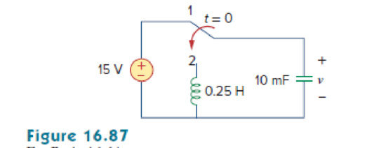
The switch in Fig. 16.87 moves from position 1 to position 2 at t = 0. Find v(t), for all t > 0.
Expert Solution & Answer
Want to see the full answer?
Check out a sample textbook solution
Students have asked these similar questions
x(t)
h(t)
t
b)
x[n] = u[n] – u[n – 5]
h[n] = 2(u[n] – u[n – 4])
Note: Use graphical technique to solve the problem.
CS CamScanner - Wgo guall
You are required to design a PID controller for the following system. All of the calculations must be
shown completely to obtain the P-I-D values.:
R(s) +
K
(s + 1)(s + 2)(s + 3)(s+4)
C(s)
The minimum sum-of-
products for the following
function
isF(A,B,C,D,E)=[m(0,1,15,16,17
) +[d(14,24,25,30,31) using
Quine - McClusky method
Chapter 16 Solutions
Fundamentals of Electric Circuits
Ch. 16.2 - Determine vo(t) in the circuit of Fig. 16.6,...Ch. 16.2 - Prob. 2PPCh. 16.2 - Prob. 3PPCh. 16.3 - For the circuit shown in Fig. 16.12 with the same...Ch. 16.3 - Prob. 5PPCh. 16.3 - The initial energy in the circuit of Fig. 16.17 is...Ch. 16.4 - Prob. 7PPCh. 16.4 - Prob. 8PPCh. 16.4 - Prob. 9PPCh. 16.5 - Obtain the state variable model for the circuit...
Ch. 16.5 - Prob. 11PPCh. 16.5 - Prob. 12PPCh. 16.6 - For what value of is the circuit in Fig. 16.29...Ch. 16.6 - Prob. 14PPCh. 16.6 - Prob. 15PPCh. 16.6 - Synthesize the function Vo(s)Vin=2ss2+6s+10 using...Ch. 16 - Prob. 1RQCh. 16 - The current through an RL series circuit with...Ch. 16 - Prob. 3RQCh. 16 - Prob. 4RQCh. 16 - Prob. 5RQCh. 16 - Prob. 6RQCh. 16 - Prob. 7RQCh. 16 - Prob. 8RQCh. 16 - Prob. 9RQCh. 16 - Prob. 10RQCh. 16 - The current in an RLC circuit is described by...Ch. 16 - The differential equation that describes the...Ch. 16 - Prob. 3PCh. 16 - If R = 20 , L = 0.6 H, what value of C will make...Ch. 16 - The responses of a series RLC circuit are vc(t) =...Ch. 16 - Prob. 6PCh. 16 - Prob. 7PCh. 16 - Prob. 8PCh. 16 - Prob. 9PCh. 16 - The step responses of a series RLC circuit are Vc...Ch. 16 - The step response of a parallel RLC circuit is v =...Ch. 16 - Prob. 12PCh. 16 - Prob. 13PCh. 16 - Prob. 14PCh. 16 - For the circuit in Fig. 16.38. calculate the value...Ch. 16 - The capacitor in the circuit of Fig. 16.39 is...Ch. 16 - If is(t) = 7.5e2t u(t) A in the circuit shown in...Ch. 16 - Find v(t), t 0 in the circuit of Fig. 16.41. Let...Ch. 16 - The switch in Fig. 16.42 moves from position A to...Ch. 16 - Find i(t) for t 0 in the circuit of Fig. 16.43.Ch. 16 - In the circuit of Fig. 16.44, the switch moves...Ch. 16 - Find the voltage across the capacitor as a...Ch. 16 - Obtain v (t) for t 0 in the circuit of Fig....Ch. 16 - The switch in the circuit of Fig. 16.47 has been...Ch. 16 - Calculate v(t) for t 0 in the circuit of Fig....Ch. 16 - Prob. 26PCh. 16 - Find v (t) for t 0 in the circuit in Fig. 16.50.Ch. 16 - For the circuit in Fig. 16.51, find v(t) for t 0.Ch. 16 - Prob. 29PCh. 16 - Find vo(t), for all t 0, in the circuit of Fig....Ch. 16 - Prob. 31PCh. 16 - For the network in Fig. 16.55, solve for i(t) for...Ch. 16 - Using Fig. 16.56, design a problem to help other...Ch. 16 - Prob. 34PCh. 16 - Prob. 35PCh. 16 - Prob. 36PCh. 16 - Prob. 37PCh. 16 - The switch in the circuit of Fig. 16.61 is moved...Ch. 16 - Prob. 39PCh. 16 - Prob. 40PCh. 16 - Prob. 41PCh. 16 - Prob. 42PCh. 16 - Prob. 43PCh. 16 - Prob. 44PCh. 16 - Find v(t) for t 0 in the circuit in Fig. 16.68.Ch. 16 - Prob. 46PCh. 16 - Determine io(t) in the network shown in Fig....Ch. 16 - Prob. 48PCh. 16 - Find i0(t) for t 0 in the circuit in Fig. 16.72....Ch. 16 - Prob. 50PCh. 16 - In the circuit of Fig. 16.74, find i(t) for t 0.Ch. 16 - Prob. 52PCh. 16 - In the circuit of Fig. 16.76, the switch has been...Ch. 16 - Prob. 54PCh. 16 - Prob. 55PCh. 16 - Calculate io(t) for t 0 in the network of Fig....Ch. 16 - Prob. 57PCh. 16 - Prob. 58PCh. 16 - Find vo(t) in the circuit of Fig. 16.82 if vx(0) =...Ch. 16 - Prob. 60PCh. 16 - Prob. 61PCh. 16 - Using Fig. 16.85, design a problem to help other...Ch. 16 - Consider the parallel RLC circuit of Fig. 16.86....Ch. 16 - The switch in Fig. 16.87 moves from position 1 to...Ch. 16 - For the RLC circuit shown in Fig. 16.88, find the...Ch. 16 - For the op amp circuit in Fig. 16.89, find v0(t)...Ch. 16 - Given the op amp circuit in Fig. 16.90, if v1(0+)...Ch. 16 - Prob. 68PCh. 16 - Prob. 69PCh. 16 - Using Fig. 16.93, design a problem to help other...Ch. 16 - Prob. 71PCh. 16 - The transfer function of a system is H(s)=s23s+1...Ch. 16 - Prob. 73PCh. 16 - Design a problem to help other students better...Ch. 16 - Prob. 75PCh. 16 - For the circuit in Fig. 16.95, find H(s) =...Ch. 16 - Obtain the transfer function H(s) = VoVs for the...Ch. 16 - Prob. 78PCh. 16 - For the circuit in Fig. 16.97, find: (a) I1/Vs (b)...Ch. 16 - Refer to the network in Fig. 16.98. Find the...Ch. 16 - Prob. 81PCh. 16 - Prob. 82PCh. 16 - Refer to the RL circuit in Fig. 16.101. Find: (a)...Ch. 16 - A parallel RL circuit has R = 4 and L = 1 H. The...Ch. 16 - Prob. 85PCh. 16 - Prob. 86PCh. 16 - Prob. 87PCh. 16 - Prob. 88PCh. 16 - Develop the state equations for the circuit shown...Ch. 16 - Prob. 90PCh. 16 - Prob. 91PCh. 16 - Prob. 92PCh. 16 - Prob. 93PCh. 16 - Prob. 94PCh. 16 - Prob. 95PCh. 16 - Prob. 96PCh. 16 - A system is formed by cascading two systems as...Ch. 16 - Determine whether the op amp circuit in Fig....Ch. 16 - It is desired realize the transfer function...Ch. 16 - Prob. 100PCh. 16 - Prob. 101PCh. 16 - Synthesize the transfer function...Ch. 16 - Prob. 103CPCh. 16 - Prob. 104CPCh. 16 - Prob. 105CP
Knowledge Booster


Learn more about
Need a deep-dive on the concept behind this application? Look no further. Learn more about this topic, electrical-engineering and related others by exploring similar questions and additional content below.Similar questions
- * Define the state variables as in the block diagram: R(s) X₂(s) (s+1) X₂(s) 10 X,(s) Y(s) (s+3)arrow_forwardWhich of the following is a minimum sum-of-products expression for function F(a,b.c,d,e) represented by the following K-Map: ab cde 1 1 X 1 1 1 X 1 o b'de + ab'd' + a'bce' + a'bd'e + bc'de' o b'cde + ab'd' + a'bc + bc'de' + b'c'de o bc'd'e' + a'bd + ab'c' + b'cd'e + bcd'e' o bc'd'e' + a'bd + ab'c'e + ab'de' + b'cd'e + bcd'e o bd'e' + a'bd + ab'c'e + ab'de' + b'cd'e o abd'e' + a'bd + ab'c'e + ab'c'd + b'cd'e o bd'e' + a'bd + ab'c' + b'cd'e 1. 1. 1. 1.arrow_forwardFind State diagram in signal fiow and block diagram format mỹ(t) + bỳ(t) + ky(t) = u(t) r; (1) = y(e) x2(t) = ý(t)arrow_forward
- Consider the function given below. Determine whether the given function is causal and BIBO-stable. x(t) = 4 rect (t/2) Please show workarrow_forward9 the rule An LTI system is described by ylt) = x(t) - x(e) de t-I Find the imputse response of the System.arrow_forwardExample 11: According to Routh-Hurwitz criterion discuss the stability of the system represent in the block diagram below: R(s) E(s) K S+13 C(s) S+3 S(S+7)arrow_forward
- Find the canonical sum of products and product of sums expression for the function F =X1 X2 X3 + X1 X3 X4 + X1 X2 X4arrow_forward(c) Find the expression for iz(1) for t> 0 s. UTM The switch in the circuit of switch opened. UTM (b) Find the expression for ve(t) and sketch ve(t) for t> 0. Att=0 s, the 3 UTM O 5 UTM S UTM UTM & UTM & UTM 5 UTM 6 ko & UTM UTM 2 kn uF 4 k2 M 5 UTM t=0 S UTM &UTM UTM ww 5 UTM UTM Q.2 The switch in Figure Q.2 has been in position 4' for a long time. At t = 0 s t 24 V 4 k2 4 k2 S UTM position 'B'. swit S UTM UTM & UTM & UTM TM 8 UTM S UTM &UTM & UTM & UTM 5 UTM 8 UTM UTM 8 UTM B. UTM 5 UTM UTM & UTM 10n - UTAUTM/ 5 V 10 2 SM & UTM 20 mH Figure Q.2arrow_forwardFind the node voltage equation of VL(t)arrow_forward
- Check whether the following mathematical representation system is static or dynamic: 1-y(t)=-x(t) 2- y(t) x(0.5t) 3- y(t) 2r(vt) 4y(t) x(t) %23 solve 3 4arrow_forwardR X For the RL circuit, find the mathematical model (input-output relationship) if the output is the resistor voltage, VR(t)=y(t) and R=17 O, L=10 H. O a. x(t) = y(t)+ 0,59y(t) O b. x(t) = y(t) + 0,59y(t) O c. X'(t) = y(t)+ 1,70y(t) O d. x(t) = y(t)+ 1,70y'(t) O e. x'(t) = y'(t)+ 1,70y'(t) O f.x'(t) = y'(t) + 0,59y(t) O g. x(t) = y(t)+ 0,59y'(t) O h. x'(t) = y'(t) + 1,70y(t)arrow_forwardSimulate the output expression of the circuit and write down your observation X= (A + B )C + (D + E)Farrow_forward
arrow_back_ios
SEE MORE QUESTIONS
arrow_forward_ios
Recommended textbooks for you
 Introductory Circuit Analysis (13th Edition)Electrical EngineeringISBN:9780133923605Author:Robert L. BoylestadPublisher:PEARSON
 Delmar's Standard Textbook Of ElectricityElectrical EngineeringISBN:9781337900348Author:Stephen L. HermanPublisher:Cengage Learning
 Programmable Logic ControllersElectrical EngineeringISBN:9780073373843Author:Frank D. PetruzellaPublisher:McGraw-Hill Education
 Fundamentals of Electric CircuitsElectrical EngineeringISBN:9780078028229Author:Charles K Alexander, Matthew SadikuPublisher:McGraw-Hill Education
 Electric Circuits. (11th Edition)Electrical EngineeringISBN:9780134746968Author:James W. Nilsson, Susan RiedelPublisher:PEARSON
 Engineering ElectromagneticsElectrical EngineeringISBN:9780078028151Author:Hayt, William H. (william Hart), Jr, BUCK, John A.Publisher:Mcgraw-hill Education,
Introductory Circuit Analysis (13th Edition)
Electrical Engineering
ISBN:9780133923605
Author:Robert L. Boylestad
Publisher:PEARSON
Delmar's Standard Textbook Of Electricity
Electrical Engineering
ISBN:9781337900348
Author:Stephen L. Herman
Publisher:Cengage Learning
Programmable Logic Controllers
Electrical Engineering
ISBN:9780073373843
Author:Frank D. Petruzella
Publisher:McGraw-Hill Education
Fundamentals of Electric Circuits
Electrical Engineering
ISBN:9780078028229
Author:Charles K Alexander, Matthew Sadiku
Publisher:McGraw-Hill Education
Electric Circuits. (11th Edition)
Electrical Engineering
ISBN:9780134746968
Author:James W. Nilsson, Susan Riedel
Publisher:PEARSON
Engineering Electromagnetics
Electrical Engineering
ISBN:9780078028151
Author:Hayt, William H. (william Hart), Jr, BUCK, John A.
Publisher:Mcgraw-hill Education,
Systems and Simulation - Lecture 3: Modelling of Mechanical systems; Author: bioMechatronics Lab;https://www.youtube.com/watch?v=fMcDdyoC9mA;License: Standard Youtube License