
Fundamentals of Electric Circuits
6th Edition
ISBN: 9780078028229
Author: Charles K Alexander, Matthew Sadiku
Publisher: McGraw-Hill Education
expand_more
expand_more
format_list_bulleted
Videos
Textbook Question
Chapter 16.5, Problem 10PP
Obtain the state variable model for the circuit shown in Fig. 16.23. Let R1 = 1, R2 = 2, C = 0.5, and L = 0.2 and obtain the transfer function.
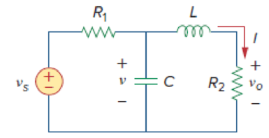
Figure 16.23
Expert Solution & Answer
Want to see the full answer?
Check out a sample textbook solution
Students have asked these similar questions
Choose the values of R1 and R2 in Fig. P16.133 to set I3 = 300 A and I1 = 75 A if VCC = VEE = 15 V. What is I2? Q136: (a) Based on the schematic in Fig. 16.46, what are the minimum values of VCC and VEE needed for proper operation of A741 amplifier? (b) What are the minimum values of VCC and VEE needed to have at least a ±1-V common-mode input range in the amplifier?
When designing P, PI, PID controller, which of the following is the method in which experimentally determined ratios are used?
A
Nyquist
B
Routh-Hurwitz
C
Bode
D
Critical Gain
E
Ziegler-Nichols
DESIGN A 16X1 MUX IN ORDER TO SATISFY THE FUNCTION F(A,B,C,D)=SUM(0,3,6,7,8,10,13,15) USING:
B) 4X1 MULTIPLEXERS
Chapter 16 Solutions
Fundamentals of Electric Circuits
Ch. 16.2 - Determine vo(t) in the circuit of Fig. 16.6,...Ch. 16.2 - Prob. 2PPCh. 16.2 - Prob. 3PPCh. 16.3 - For the circuit shown in Fig. 16.12 with the same...Ch. 16.3 - Prob. 5PPCh. 16.3 - The initial energy in the circuit of Fig. 16.17 is...Ch. 16.4 - Prob. 7PPCh. 16.4 - Prob. 8PPCh. 16.4 - Prob. 9PPCh. 16.5 - Obtain the state variable model for the circuit...
Ch. 16.5 - Prob. 11PPCh. 16.5 - Prob. 12PPCh. 16.6 - For what value of is the circuit in Fig. 16.29...Ch. 16.6 - Prob. 14PPCh. 16.6 - Prob. 15PPCh. 16.6 - Synthesize the function Vo(s)Vin=2ss2+6s+10 using...Ch. 16 - Prob. 1RQCh. 16 - The current through an RL series circuit with...Ch. 16 - Prob. 3RQCh. 16 - Prob. 4RQCh. 16 - Prob. 5RQCh. 16 - Prob. 6RQCh. 16 - Prob. 7RQCh. 16 - Prob. 8RQCh. 16 - Prob. 9RQCh. 16 - Prob. 10RQCh. 16 - The current in an RLC circuit is described by...Ch. 16 - The differential equation that describes the...Ch. 16 - Prob. 3PCh. 16 - If R = 20 , L = 0.6 H, what value of C will make...Ch. 16 - The responses of a series RLC circuit are vc(t) =...Ch. 16 - Prob. 6PCh. 16 - Prob. 7PCh. 16 - Prob. 8PCh. 16 - Prob. 9PCh. 16 - The step responses of a series RLC circuit are Vc...Ch. 16 - The step response of a parallel RLC circuit is v =...Ch. 16 - Prob. 12PCh. 16 - Prob. 13PCh. 16 - Prob. 14PCh. 16 - For the circuit in Fig. 16.38. calculate the value...Ch. 16 - The capacitor in the circuit of Fig. 16.39 is...Ch. 16 - If is(t) = 7.5e2t u(t) A in the circuit shown in...Ch. 16 - Find v(t), t 0 in the circuit of Fig. 16.41. Let...Ch. 16 - The switch in Fig. 16.42 moves from position A to...Ch. 16 - Find i(t) for t 0 in the circuit of Fig. 16.43.Ch. 16 - In the circuit of Fig. 16.44, the switch moves...Ch. 16 - Find the voltage across the capacitor as a...Ch. 16 - Obtain v (t) for t 0 in the circuit of Fig....Ch. 16 - The switch in the circuit of Fig. 16.47 has been...Ch. 16 - Calculate v(t) for t 0 in the circuit of Fig....Ch. 16 - Prob. 26PCh. 16 - Find v (t) for t 0 in the circuit in Fig. 16.50.Ch. 16 - For the circuit in Fig. 16.51, find v(t) for t 0.Ch. 16 - Prob. 29PCh. 16 - Find vo(t), for all t 0, in the circuit of Fig....Ch. 16 - Prob. 31PCh. 16 - For the network in Fig. 16.55, solve for i(t) for...Ch. 16 - Using Fig. 16.56, design a problem to help other...Ch. 16 - Prob. 34PCh. 16 - Prob. 35PCh. 16 - Prob. 36PCh. 16 - Prob. 37PCh. 16 - The switch in the circuit of Fig. 16.61 is moved...Ch. 16 - Prob. 39PCh. 16 - Prob. 40PCh. 16 - Prob. 41PCh. 16 - Prob. 42PCh. 16 - Prob. 43PCh. 16 - Prob. 44PCh. 16 - Find v(t) for t 0 in the circuit in Fig. 16.68.Ch. 16 - Prob. 46PCh. 16 - Determine io(t) in the network shown in Fig....Ch. 16 - Prob. 48PCh. 16 - Find i0(t) for t 0 in the circuit in Fig. 16.72....Ch. 16 - Prob. 50PCh. 16 - In the circuit of Fig. 16.74, find i(t) for t 0.Ch. 16 - Prob. 52PCh. 16 - In the circuit of Fig. 16.76, the switch has been...Ch. 16 - Prob. 54PCh. 16 - Prob. 55PCh. 16 - Calculate io(t) for t 0 in the network of Fig....Ch. 16 - Prob. 57PCh. 16 - Prob. 58PCh. 16 - Find vo(t) in the circuit of Fig. 16.82 if vx(0) =...Ch. 16 - Prob. 60PCh. 16 - Prob. 61PCh. 16 - Using Fig. 16.85, design a problem to help other...Ch. 16 - Consider the parallel RLC circuit of Fig. 16.86....Ch. 16 - The switch in Fig. 16.87 moves from position 1 to...Ch. 16 - For the RLC circuit shown in Fig. 16.88, find the...Ch. 16 - For the op amp circuit in Fig. 16.89, find v0(t)...Ch. 16 - Given the op amp circuit in Fig. 16.90, if v1(0+)...Ch. 16 - Prob. 68PCh. 16 - Prob. 69PCh. 16 - Using Fig. 16.93, design a problem to help other...Ch. 16 - Prob. 71PCh. 16 - The transfer function of a system is H(s)=s23s+1...Ch. 16 - Prob. 73PCh. 16 - Design a problem to help other students better...Ch. 16 - Prob. 75PCh. 16 - For the circuit in Fig. 16.95, find H(s) =...Ch. 16 - Obtain the transfer function H(s) = VoVs for the...Ch. 16 - Prob. 78PCh. 16 - For the circuit in Fig. 16.97, find: (a) I1/Vs (b)...Ch. 16 - Refer to the network in Fig. 16.98. Find the...Ch. 16 - Prob. 81PCh. 16 - Prob. 82PCh. 16 - Refer to the RL circuit in Fig. 16.101. Find: (a)...Ch. 16 - A parallel RL circuit has R = 4 and L = 1 H. The...Ch. 16 - Prob. 85PCh. 16 - Prob. 86PCh. 16 - Prob. 87PCh. 16 - Prob. 88PCh. 16 - Develop the state equations for the circuit shown...Ch. 16 - Prob. 90PCh. 16 - Prob. 91PCh. 16 - Prob. 92PCh. 16 - Prob. 93PCh. 16 - Prob. 94PCh. 16 - Prob. 95PCh. 16 - Prob. 96PCh. 16 - A system is formed by cascading two systems as...Ch. 16 - Determine whether the op amp circuit in Fig....Ch. 16 - It is desired realize the transfer function...Ch. 16 - Prob. 100PCh. 16 - Prob. 101PCh. 16 - Synthesize the transfer function...Ch. 16 - Prob. 103CPCh. 16 - Prob. 104CPCh. 16 - Prob. 105CP
Knowledge Booster


Learn more about
Need a deep-dive on the concept behind this application? Look no further. Learn more about this topic, electrical-engineering and related others by exploring similar questions and additional content below.Similar questions
- Give an example of the transformation of a mechanical system in the subject of the system Modeling of Transfer function modelsarrow_forwardWrite a dataflow-style Verilog module Vr74x182 that performs the same functionas the 74x182 lookahead carry circuit, but with active-high generate and propagate signalsarrow_forwardProcess systems analysis Does a transfer function provide a model of the output behavior for any input assuming that all the initial conditionsa are zero? Why or why not?arrow_forward
- Predict output of a microcontroller with its port P0 connected to LEDs based on the following program. Give your own analysis for each line of the program. BACK: MOV A, #55H MOV P0, A ACALL DELAY MOV A, #0AAH MOV P0, A ACALL DELAY SJMP BACK DELAY: MOV R3, #200 HERE: DJNZ R3, HERE RETarrow_forward1. Explain how a RC circuit behaves as a differentiator and an integrator with the help of circuits and mathematical expressions. 2. What do you understand by TTL? Explain the working of 3-input NAND gate using TTL with circuit diagram and truth table. 3. What do you understand by DAC? Explain the working of 4-bit R-2R ladder DẶC with diagram.arrow_forward• Estimate the output voltage of the DAC in the fig (a) below if the sequence of 4 – bit codes represented by the waveforms in fig (b) is applied to the inputs. [HIGH = 1, and LOW = 0 and the LSB is Do]. %3D R = 37.5KN 1 2 3 4 5 6 7 8 9 10 11 12 13 14 15 D3 W + 5V - Do Rf 2R = 75KN + 5V D1 12KN D2 W 4R = 150KS + 5V D2 Vo 8R = 300KN +5V D3 trtr tIt Do 2n-1 fig (a)arrow_forward
- DESIGN A 16X1 MUX USING ONLY ONE 8X1 MUX SO AS TO SATISFY THE FUNCTION F(A,B,C,D)= SUM( 1,3,4,6,8,10,12,14 ), D IS THE MSB AND CONTROLLING FACTOR( DESIGN W.R.T. D) IMPLIMENT THE CIRCUIT USING CIRCUIT MAKER AND UPLOAD TO ELEARNING. 0785363649arrow_forwardDetermine the transfer function and the block diagram of the following systems. Explain in detail the steps to follow to reach the result Consider that the input signal is ?i(?) and the output signal is ?o(t)arrow_forward16.6 Design an output voltage-clamping circuit as shown in Fig. 16.14(a) so that the slope of the transfer char- acteristic is S = vo vs = 20, Vo(max) = 6.7 V, and Vo(min) = -8.7 V. Determine the zener voltages Vzi and V22. Assume Vp = 0.7 V. P S +== Vd A = ∞ I M R₁ Vx RE V22 Vz1 Voarrow_forward
- 16.13 Design a noninverting Schmitt trigger as in Fig. 16.28(a) so that Vth = |+Vth = |-Vth = 5 V. Assume Vsat = |- Vsat = 12 V. P R₁ Vd if + RF A R₁ = R₁ || RF + VOarrow_forwardConsider a discrete LTI system with the following input x[n] and theimpulse response h[n], a) Find the output signal y[n]=x[n]*h[n]b) Plot the output signal y[n].arrow_forwardA) The probabilities for two events, C and D: P(C)=0.60, P(D)=0.40, P(CUD) =0.65 Are the events, C and D, independent in this situation? Prove it?arrow_forward
arrow_back_ios
SEE MORE QUESTIONS
arrow_forward_ios
Recommended textbooks for you
 Introductory Circuit Analysis (13th Edition)Electrical EngineeringISBN:9780133923605Author:Robert L. BoylestadPublisher:PEARSON
 Delmar's Standard Textbook Of ElectricityElectrical EngineeringISBN:9781337900348Author:Stephen L. HermanPublisher:Cengage Learning
 Programmable Logic ControllersElectrical EngineeringISBN:9780073373843Author:Frank D. PetruzellaPublisher:McGraw-Hill Education
 Fundamentals of Electric CircuitsElectrical EngineeringISBN:9780078028229Author:Charles K Alexander, Matthew SadikuPublisher:McGraw-Hill Education
 Electric Circuits. (11th Edition)Electrical EngineeringISBN:9780134746968Author:James W. Nilsson, Susan RiedelPublisher:PEARSON
 Engineering ElectromagneticsElectrical EngineeringISBN:9780078028151Author:Hayt, William H. (william Hart), Jr, BUCK, John A.Publisher:Mcgraw-hill Education,
Introductory Circuit Analysis (13th Edition)
Electrical Engineering
ISBN:9780133923605
Author:Robert L. Boylestad
Publisher:PEARSON
Delmar's Standard Textbook Of Electricity
Electrical Engineering
ISBN:9781337900348
Author:Stephen L. Herman
Publisher:Cengage Learning
Programmable Logic Controllers
Electrical Engineering
ISBN:9780073373843
Author:Frank D. Petruzella
Publisher:McGraw-Hill Education
Fundamentals of Electric Circuits
Electrical Engineering
ISBN:9780078028229
Author:Charles K Alexander, Matthew Sadiku
Publisher:McGraw-Hill Education
Electric Circuits. (11th Edition)
Electrical Engineering
ISBN:9780134746968
Author:James W. Nilsson, Susan Riedel
Publisher:PEARSON
Engineering Electromagnetics
Electrical Engineering
ISBN:9780078028151
Author:Hayt, William H. (william Hart), Jr, BUCK, John A.
Publisher:Mcgraw-hill Education,
Introduction to Logic Gates; Author: Computer Science;https://www.youtube.com/watch?v=fw-N9P38mi4;License: Standard youtube license