
Introductory Circuit Analysis (13th Edition)
13th Edition
ISBN: 9780133923605
Author: Robert L. Boylestad
Publisher: PEARSON
expand_more
expand_more
format_list_bulleted
Concept explainers
Videos
Textbook Question
Chapter 7, Problem 13P
Find the value of each resistor for the network of Fig. 7.76.
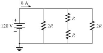
Fig. 7.76
Expert Solution & Answer
Want to see the full answer?
Check out a sample textbook solution
Students have asked these similar questions
14. For the network of Fig. 7.86, Vp = 12 V. Determine:
a. Ip.
b. Vs and Vps-
c. Vg and VGs.
d. Vp.
3. For the network of Fig. 7.85 , determine:
a. VG.
b. ID and VGS.
c. VD and VS.
d. VDS.
O 20 V
2.2 kn
910 kQ
Dss = 10 mA
V, =-3.5 V
Vasa
110 kQ
1.1 ka
For the given circuit in Fig. 7, the voltage across the element is required to be measured using two voltmeters whose internal resistances are 300KW and 6MW.
1.a) Calculate the correct value.
b) Calculate the values measured by each voltmeter and corresponding errors
Chapter 7 Solutions
Introductory Circuit Analysis (13th Edition)
Ch. 7 - Which elements (individual elements, not...Ch. 7 - Repeat Problem 1 for the networks of Fig. 7.65....Ch. 7 - Determine RT for the networks in Fig. 7.66. Fig....Ch. 7 - Determine RT for the networks in Fig. 7.67. Fig....Ch. 7 - Find the total resistance for the configuration of...Ch. 7 - The total resistance RT for the network of Fig....Ch. 7 - For the network in Fig. 7.70. a. Does...Ch. 7 - For the network in Fig. 7.71: a. Determine RT. b....Ch. 7 - For the network of Fig. 7.72: a. find the currents...Ch. 7 - For the network of Fig. 7.73: Find the voltages V3...
Ch. 7 - For the network of Fig. 7.74 a. Find the voltages...Ch. 7 - For the circuit board in Fig. 7.75: Find the total...Ch. 7 - Find the value of each resistor for the network of...Ch. 7 - Find the resistance RT for the network of Fig....Ch. 7 - For the network in Fig. 7.78: a. Find currents...Ch. 7 - a. Find the magnitude and direction of the...Ch. 7 - Determine the currents I1andI2 for the network in...Ch. 7 - For the network in Fig. 7.81: a. Determine the...Ch. 7 - For the network in Fig. 7.82: a. Determine the...Ch. 7 - Determine the dc levels for the transistor network...Ch. 7 - For the network in Fig. 7.84: Determine the...Ch. 7 - For the network in Fig. 7.852 Determine RT by...Ch. 7 - For the network of Fig. 7.86: a. Find the voltages...Ch. 7 - For the network in Fig. 7.87: a. Determine the...Ch. 7 - For the network in Fig. 7.88 find the resistance...Ch. 7 - If all the resistors of the cube in Fig. 7.89 are...Ch. 7 - For the ladder network in Fig. 7.90: a. Find the...Ch. 7 - For the ladder network in Fig. 7.91: a. Determine...Ch. 7 - Given the voltage divider supply in Fig. 7.92: a....Ch. 7 - Determine the voltage divider supply resistors for...Ch. 7 - A studio lamp requires 40 V at 50 mA to burn...Ch. 7 - For the system in Fig. 7.94 a. At first exposure,...Ch. 7 - For the potentiometer in Fig. 7.95: a. What are...Ch. 7 - Prob. 34PCh. 7 - Given the voltmeter reading V = 27 V in Fig. 7.97...Ch. 7 - Determine the power delivered to the 6 load in...Ch. 7 - For the multiple ladder configuration in Fig....Ch. 7 - An iron-vane movement is rated 1 mA, 100 . a. What...Ch. 7 - Using a 50 A, 1000 movement, design a multirange...Ch. 7 - An iron-vane movement is rated 50 A , 1000 a....Ch. 7 - Using a 1 mA, 1000 movement, design a multirange...Ch. 7 - A digital meter has an internal resistance of 10 M...Ch. 7 - a. Design a series ohmmeter using a 100 A, 1000...Ch. 7 - Prob. 44PCh. 7 - Determine the reading of the ohmmeter for each...Ch. 7 - Using PSpice or Multisim, verify the result of...Ch. 7 - Using PSpice or Multisim, Confirm the solutions of...Ch. 7 - Using PSpice or Multisim, verify the result of...Ch. 7 - Using PSpice or Multisim, find voltage V6 of Fig....Ch. 7 - Using PSpice or Multisim, find voltages Vb and Vc...
Additional Engineering Textbook Solutions
Find more solutions based on key concepts
Find I0 and I1 in the circuit in Fig.P2.12.
Basic Engineering Circuit Analysis
Identify the type of input and output configuration for each diff-amp in Figure 18-35.
Electronics Fundamentals: Circuits, Devices & Applications
Does the severity of an electric shock increase ordecrease with eh of the following changes? a. A decrease in t...
Electric Motors and Control Systems
Assume a telephone signal travels through a cable at two-thirds the speed of light. How long does it take the s...
Electric Circuits (10th Edition)
Design an ideal inverting op-amp circuit such that the voltage gain is Av=25 . The maximum current in any resis...
Microelectronics: Circuit Analysis and Design
A constant voltage of 10V is applied to a 50H inductance, as shown in Figure P3.51 Figure P3 51 The current in ...
Electrical Engineering: Principles & Applications (7th Edition)
Knowledge Booster


Learn more about
Need a deep-dive on the concept behind this application? Look no further. Learn more about this topic, electrical-engineering and related others by exploring similar questions and additional content below.Similar questions
- For the network of Fig. 7.86, Vp = 12 V. Determine: a. Ip. b. Vs and Vps- c. Vg and VGs- d. Vp. 18 V 2 k2 O Vp = 12 V + VG 12 VoMw VDS Ipss = 8 mA 680 k2 VGS Vs '110 k2 0.68 k2arrow_forwardQ 2) For the network in Fig. 7.64: a. Find the total resistance R, b. Find the source current I, and currents /, and Iy. c. Find current ls. d. Find voltages V; and Va. Ry R 120 40 R4 14 V V, R 120 Ryarrow_forwardFor the network of Fig. 7.91, VD 9 V. Determine:to. a. ID.b. VS and VDS.c. VG and VGS.d. VP.arrow_forward
- 1:0r 1%EM とイ l المكالمات H.W -2 6. For the circuit board in Fig. 7.66: a. Find the total resistance R, of the configuration. b. Find the current drawn from the supply if the applied voltage is 48 V. c. Find the reading of the applied voltmeter. 6.8 kf2 V 3.3 kfl 2 k Rr 1 k -24 kf 48 V FIG, 7,66 Problem 6.arrow_forward4_59407736683332... Problem II SERIES-PARALLEL NETWORKS *21. For the network of Fig. 7.84: a. Determine the current /. b. Calculate the open-circuit voltage V *22. For the network of Fig. 7.85, find the resistance current through it is 2 A. 20 V R E120 80 120 V 18 V 60 R200 30 FIG. 7.84 Problem 21. FIG. 7.85 Problem 22arrow_forward6. For the circuit board in Fig. 7.66: a. Find the total resistance R, of the configuration. b. Find the current drawn from the supply if the applied voltage is 48 V. c. Find the reading of the applied voltmeter. 10 6.8 kl 1.2 k 3.3 k 2 k RT 48 V 1 k 24 kf FIG. 7.66 Problem 6.arrow_forward
- 4. ror une network in Fig. 7.64: a. Find the total resistance RT. b. Find the source current I, and currents I, and I3. c. Find current Iş. d. Find voltages V2 and V4. 13 R3 R1 12 N R4 4Ω + 12 0 E 14 V V2 R2 60 V4 RT + +arrow_forward*21. For the network of Fig. 7.93, determine: a. Ipo and VGSo b. Vps and Vs. 18 V 2.2 k2 Ipss = 8 mA Vp = -8 V Vaso 0.39 k2 6-4 V FIG. 7.93 Problem 21.arrow_forwardFET BIASING 33. For the network of Fig. 7.102, determine: a. Ip, and VGso' b. Vps- c. Vp. C9 9-16 V 2 k2 1 M2 VGs (Th) = -3 V Ip (on) = 4 mA VGs (on) = -7 V Vase FIG. 7.102arrow_forward
- Given VDS = 4 V for the network of Fig. 7.89, determine: a. IDb. VD and VS c. VGarrow_forwardDetermine IDQ for the network of Fig. 7.80 using a purely mathematical approacHarrow_forward*11. Find Vs for the network of Fig. 7.84. 20 V 2.2 k Ip Ipss = 4.5 mA Vp =-5 V Vps I pss = 6 mA Vp = -6 V 14 V 2.2 kQ 0.68 k2 0.39 k2 -4 V FIG. 7.83 FIG. 7.84 Problem 10. Problem 11.arrow_forward
arrow_back_ios
SEE MORE QUESTIONS
arrow_forward_ios
Recommended textbooks for you
 Introductory Circuit Analysis (13th Edition)Electrical EngineeringISBN:9780133923605Author:Robert L. BoylestadPublisher:PEARSON
 Delmar's Standard Textbook Of ElectricityElectrical EngineeringISBN:9781337900348Author:Stephen L. HermanPublisher:Cengage Learning
 Programmable Logic ControllersElectrical EngineeringISBN:9780073373843Author:Frank D. PetruzellaPublisher:McGraw-Hill Education
 Fundamentals of Electric CircuitsElectrical EngineeringISBN:9780078028229Author:Charles K Alexander, Matthew SadikuPublisher:McGraw-Hill Education
 Electric Circuits. (11th Edition)Electrical EngineeringISBN:9780134746968Author:James W. Nilsson, Susan RiedelPublisher:PEARSON
 Engineering ElectromagneticsElectrical EngineeringISBN:9780078028151Author:Hayt, William H. (william Hart), Jr, BUCK, John A.Publisher:Mcgraw-hill Education,
Introductory Circuit Analysis (13th Edition)
Electrical Engineering
ISBN:9780133923605
Author:Robert L. Boylestad
Publisher:PEARSON
Delmar's Standard Textbook Of Electricity
Electrical Engineering
ISBN:9781337900348
Author:Stephen L. Herman
Publisher:Cengage Learning
Programmable Logic Controllers
Electrical Engineering
ISBN:9780073373843
Author:Frank D. Petruzella
Publisher:McGraw-Hill Education
Fundamentals of Electric Circuits
Electrical Engineering
ISBN:9780078028229
Author:Charles K Alexander, Matthew Sadiku
Publisher:McGraw-Hill Education
Electric Circuits. (11th Edition)
Electrical Engineering
ISBN:9780134746968
Author:James W. Nilsson, Susan Riedel
Publisher:PEARSON
Engineering Electromagnetics
Electrical Engineering
ISBN:9780078028151
Author:Hayt, William H. (william Hart), Jr, BUCK, John A.
Publisher:Mcgraw-hill Education,
Current Divider Rule; Author: Neso Academy;https://www.youtube.com/watch?v=hRU1mKWUehY;License: Standard YouTube License, CC-BY