
Introductory Circuit Analysis (13th Edition)
13th Edition
ISBN: 9780133923605
Author: Robert L. Boylestad
Publisher: PEARSON
expand_more
expand_more
format_list_bulleted
Concept explainers
Videos
Textbook Question
Chapter 7, Problem 6P
The total resistance RT for the network of Fig. 7.69. is 7.2
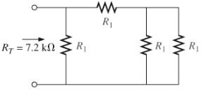
Fig. 7.69
Expert Solution & Answer

Learn your wayIncludes step-by-step video

schedule03:59
Students have asked these similar questions
Q 2)
For the network in Fig. 7.64:
a. Find the total resistance R,
b. Find the source current I, and currents /, and Iy.
c. Find current ls.
d. Find voltages V; and Va.
Ry
R
120
40
R4
14 V
V, R
120
Ry
For the network of Fig. 7.86, Vp = 12 V. Determine:
a. Ip.
b. Vs and Vps-
c. Vg and VGs-
d. Vp.
18 V
2 k2
O Vp = 12 V
+
VG
12 VoMw
VDS
Ipss = 8 mA
680 k2
VGS
Vs
'110 k2
0.68 k2
For the ladder network in fig . 7.90
A. Find the current I
B.Find the current I7
C.determine the voltage V3 V5 and V7
D. Calculate the power delivered to R7 and compare it to the power delivered by the 240 V supply
Chapter 7 Solutions
Introductory Circuit Analysis (13th Edition)
Ch. 7 - Which elements (individual elements, not...Ch. 7 - Repeat Problem 1 for the networks of Fig. 7.65....Ch. 7 - Determine RT for the networks in Fig. 7.66. Fig....Ch. 7 - Determine RT for the networks in Fig. 7.67. Fig....Ch. 7 - Find the total resistance for the configuration of...Ch. 7 - The total resistance RT for the network of Fig....Ch. 7 - For the network in Fig. 7.70. a. Does...Ch. 7 - For the network in Fig. 7.71: a. Determine RT. b....Ch. 7 - For the network of Fig. 7.72: a. find the currents...Ch. 7 - For the network of Fig. 7.73: Find the voltages V3...
Ch. 7 - For the network of Fig. 7.74 a. Find the voltages...Ch. 7 - For the circuit board in Fig. 7.75: Find the total...Ch. 7 - Find the value of each resistor for the network of...Ch. 7 - Find the resistance RT for the network of Fig....Ch. 7 - For the network in Fig. 7.78: a. Find currents...Ch. 7 - a. Find the magnitude and direction of the...Ch. 7 - Determine the currents I1andI2 for the network in...Ch. 7 - For the network in Fig. 7.81: a. Determine the...Ch. 7 - For the network in Fig. 7.82: a. Determine the...Ch. 7 - Determine the dc levels for the transistor network...Ch. 7 - For the network in Fig. 7.84: Determine the...Ch. 7 - For the network in Fig. 7.852 Determine RT by...Ch. 7 - For the network of Fig. 7.86: a. Find the voltages...Ch. 7 - For the network in Fig. 7.87: a. Determine the...Ch. 7 - For the network in Fig. 7.88 find the resistance...Ch. 7 - If all the resistors of the cube in Fig. 7.89 are...Ch. 7 - For the ladder network in Fig. 7.90: a. Find the...Ch. 7 - For the ladder network in Fig. 7.91: a. Determine...Ch. 7 - Given the voltage divider supply in Fig. 7.92: a....Ch. 7 - Determine the voltage divider supply resistors for...Ch. 7 - A studio lamp requires 40 V at 50 mA to burn...Ch. 7 - For the system in Fig. 7.94 a. At first exposure,...Ch. 7 - For the potentiometer in Fig. 7.95: a. What are...Ch. 7 - Prob. 34PCh. 7 - Given the voltmeter reading V = 27 V in Fig. 7.97...Ch. 7 - Determine the power delivered to the 6 load in...Ch. 7 - For the multiple ladder configuration in Fig....Ch. 7 - An iron-vane movement is rated 1 mA, 100 . a. What...Ch. 7 - Using a 50 A, 1000 movement, design a multirange...Ch. 7 - An iron-vane movement is rated 50 A , 1000 a....Ch. 7 - Using a 1 mA, 1000 movement, design a multirange...Ch. 7 - A digital meter has an internal resistance of 10 M...Ch. 7 - a. Design a series ohmmeter using a 100 A, 1000...Ch. 7 - Prob. 44PCh. 7 - Determine the reading of the ohmmeter for each...Ch. 7 - Using PSpice or Multisim, verify the result of...Ch. 7 - Using PSpice or Multisim, Confirm the solutions of...Ch. 7 - Using PSpice or Multisim, verify the result of...Ch. 7 - Using PSpice or Multisim, find voltage V6 of Fig....Ch. 7 - Using PSpice or Multisim, find voltages Vb and Vc...
Additional Engineering Textbook Solutions
Find more solutions based on key concepts
Find the equivalent capacitance between terminals x and y for each of the circuits shown in Figure P3.25. Figur...
Electrical Engineering: Principles & Applications (7th Edition)
The switch in the bottom loop of Fig. P6.1 is closed at t = 0 and then opened at a later time t1. What is the d...
Fundamentals of Applied Electromagnetics (7th Edition)
Consider the partially filled array a from Self-Test Question 18. Write some code that will place the number 42...
Java: An Introduction to Problem Solving and Programming (7th Edition)
In one approach to identifying the classes in a problem, the programmer identifies the _______ in a description...
Starting Out with Python (3rd Edition)
Determine the reactions at the supports. Prob. 4-6
Statics and Mechanics of Materials (5th Edition)
Why would it be incorrect to add the modifier const, as shown here, to the function declaration for the member ...
Problem Solving with C++ (9th Edition)
Knowledge Booster


Learn more about
Need a deep-dive on the concept behind this application? Look no further. Learn more about this topic, electrical-engineering and related others by exploring similar questions and additional content below.Similar questions
- FET BIASING 33. For the network of Fig. 7.102, determine: a. Ip, and VGso' b. Vps- c. Vp. C9 9-16 V 2 k2 1 M2 VGs (Th) = -3 V Ip (on) = 4 mA VGs (on) = -7 V Vase FIG. 7.102arrow_forward*25. For the combination network of Fig. 7.97, determine: a. VB and VG- b. Vg. c. IE, Ic, and Ip. d. Iв- e. Vc, Vs, and Vp- f. VCE- g. VDs- 2.2 k2 40 k2 OVD Dss 6 mA Vps Vp =-6 V Va.Va Vy.Vc le VCE B = 100 10 k2 VEE 1.2 k2 FIG. 7.97 Problem 25.arrow_forward11. For the series-parallel network of Fig. 7.59: a. Find the current I. R2 9. b. Find the currents I3 and I9. c. Find the current Ig. d. Find the voltage V. 50 V. R31 ab. R7 R,10 0 80 V R9 R4 = 42- R58N FIG. 7.59 Problem 11.arrow_forward
- 4_59407736683332... Problem II SERIES-PARALLEL NETWORKS *21. For the network of Fig. 7.84: a. Determine the current /. b. Calculate the open-circuit voltage V *22. For the network of Fig. 7.85, find the resistance current through it is 2 A. 20 V R E120 80 120 V 18 V 60 R200 30 FIG. 7.84 Problem 21. FIG. 7.85 Problem 22arrow_forwardQ2 o 20 V For the network of Fig. 7.85, determine: 2.2 kn a. VG- b. Ipo and VGSo c. Vp and Vs- d. Vpsg 910 k2 DO Dss = 10 mA Vp =-3.5 V VG +] Vaso 110 kΩ 1.1 k2arrow_forward1:0r 1%EM とイ l المكالمات H.W -2 6. For the circuit board in Fig. 7.66: a. Find the total resistance R, of the configuration. b. Find the current drawn from the supply if the applied voltage is 48 V. c. Find the reading of the applied voltmeter. 6.8 kf2 V 3.3 kfl 2 k Rr 1 k -24 kf 48 V FIG, 7,66 Problem 6.arrow_forward
- *11. For the series-parallel network of Fig. 7.74: R2 R6 a. Find the current I. b. Find the currents I and Ig. c. Find the current Ig. d. Find the voltage Vab 6Ω V 19 at Ro 60 1s R1 10 Ω 80 V 4Ω R = 40 Rs8N R20 FIG. 7.74 Problem 11.arrow_forwardFor the network of Fig. 7.91, VD 9 V. Determine:to. a. ID.b. VS and VDS.c. VG and VGS.d. VP.arrow_forward*21. For the network of Fig. 7.93, determine: a. Ipo and VGSo b. Vps and Vs. 18 V 2.2 k2 Ipss = 8 mA Vp = -8 V Vaso 0.39 k2 6-4 V FIG. 7.93 Problem 21.arrow_forward
- fig. 7.80 for the Gufiguration of © find the currents I2, Is andl Is 5 find the Joltages Vy and us Ri R3 Ru R6 Rs R7 Ri 302 32arrow_forwardCH. 7 6. For the circuit board in Fig. 7.66: a. Find the total resistance R, of the configuration. Ans. R¡ = 0.8 k2 b. Find the current drawn from the supply if the applied voltage is 48 V. Ans. Is 60 mA c. Find the reading of the applied voltmeter. Ans. V 19.2 V 6.8 k2 1.2 kfl 3.3 kf 2 kf2 RT 48 V 2.4 kfarrow_forward. Determine Vp and VGs for the network of Fig. 7.91 using the provided information. VD 4 V 1.8 k2 1 k2 16 V o- VGS Dss= 4 mA Vp=-6 V 3.6 kn 1.2 kNarrow_forward
arrow_back_ios
SEE MORE QUESTIONS
arrow_forward_ios
Recommended textbooks for you
 Introductory Circuit Analysis (13th Edition)Electrical EngineeringISBN:9780133923605Author:Robert L. BoylestadPublisher:PEARSON
 Delmar's Standard Textbook Of ElectricityElectrical EngineeringISBN:9781337900348Author:Stephen L. HermanPublisher:Cengage Learning
 Programmable Logic ControllersElectrical EngineeringISBN:9780073373843Author:Frank D. PetruzellaPublisher:McGraw-Hill Education
 Fundamentals of Electric CircuitsElectrical EngineeringISBN:9780078028229Author:Charles K Alexander, Matthew SadikuPublisher:McGraw-Hill Education
 Electric Circuits. (11th Edition)Electrical EngineeringISBN:9780134746968Author:James W. Nilsson, Susan RiedelPublisher:PEARSON
 Engineering ElectromagneticsElectrical EngineeringISBN:9780078028151Author:Hayt, William H. (william Hart), Jr, BUCK, John A.Publisher:Mcgraw-hill Education,
Introductory Circuit Analysis (13th Edition)
Electrical Engineering
ISBN:9780133923605
Author:Robert L. Boylestad
Publisher:PEARSON
Delmar's Standard Textbook Of Electricity
Electrical Engineering
ISBN:9781337900348
Author:Stephen L. Herman
Publisher:Cengage Learning
Programmable Logic Controllers
Electrical Engineering
ISBN:9780073373843
Author:Frank D. Petruzella
Publisher:McGraw-Hill Education
Fundamentals of Electric Circuits
Electrical Engineering
ISBN:9780078028229
Author:Charles K Alexander, Matthew Sadiku
Publisher:McGraw-Hill Education
Electric Circuits. (11th Edition)
Electrical Engineering
ISBN:9780134746968
Author:James W. Nilsson, Susan Riedel
Publisher:PEARSON
Engineering Electromagnetics
Electrical Engineering
ISBN:9780078028151
Author:Hayt, William H. (william Hart), Jr, BUCK, John A.
Publisher:Mcgraw-hill Education,
Current Divider Rule; Author: Neso Academy;https://www.youtube.com/watch?v=hRU1mKWUehY;License: Standard YouTube License, CC-BY